


|
|
|||
| Log In | |||
|
| |||
|
| |||
| |||
| |||
| |||


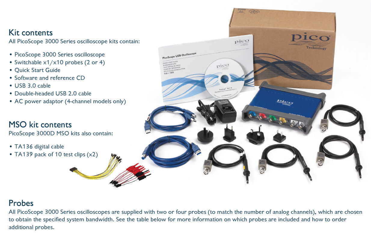
PC Oscilloscopes & Mixed Signal OscilloscopesPower, portability and performanceThe PicoScope 3000 Series USB-powered PC oscilloscopes are small, light, and portable and can easily slip into a laptop bag while offering a range of high performance specifications. These oscilloscopes offer 2 or 4 analog channels, plus 16 digital channels and a built in function / arbitrary waveform generator.
Supported by the advanced PicoScope 6 software, these devices offer an ideal, cost-effective package for many applications, including embedded systems design, research, test, education, service, and repair. High bandwidth and sampling rate Despite a compact size and low cost, there is no compromise on performance with bandwidths up to 200 MHz. This bandwidth is matched by a real-time sampling rate of up to 1 GS/s, allowing detailed display of high frequencies. For repetitive signals, the maximum effective sampling rate can be boosted to 10 GS/s by using Equivalent Time Sampling (ETS) mode. Other oscilloscopes have high maximum sampling rates, but without deep memory they cannot sustain these rates on long timebases. The PicoScope 3000 Series offers memory depths up to 512 million samples, more than any other oscilloscope in this price range, which enables the PicoScope 3406D MSO to sample at 1 GS/s all the way down to 50 ms/ div (500 ms total capture time). Managing all this data calls for some powerful tools. There’s a set of zoom buttons, plus an overview window that lets you zoom and reposition the display by simply dragging with the mouse or touchscreen. Zoom factors of several million are possible. Other tools such as the waveform buffer, mask limit test, serial decode and hardware acceleration work with the deep memory making the PicoScope 3000 series some of the most powerful oscilloscopes on the market. Deep memoryThe PicoScope 3000 Series offers memory depths up to 512 million samples, more than any other oscilloscope in this price range. 
Other oscilloscopes have high maximum sampling rates, but without deep memory they cannot sustain these rates on long timebases. Using its 512 MS buffer, the PicoScope 3406D can sample at 1 GS/s all the way down to 50 ms/ div (500 ms total capture time). Managing all this data calls for some powerful tools. There’s a set of zoom buttons, plus an overview window that lets you zoom and reposition the display by simply dragging with the mouse or touchscreen. Zoom factors of several million are possible. Other tools such as the waveform buffer, mask limit test, serial decode and hardware acceleration work with the the deep memory making the PicoScope 3000 one of the most powerful oscilloscopes on the market. Hardware Acceleration Engine (HAL3)
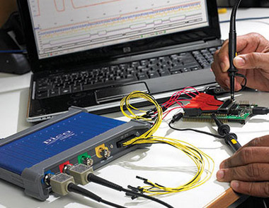
Hardware acceleration ensures fast screen Some oscilloscopes struggle when you enable deep memory, the screen update rate slows and controls become unresponsive. We avoid this limitation by the use of a dedicated hardware acceleration engine inside the oscilloscope. Its massively parallel design effectively creates the waveform image to be displayed on the PC screen and allows the continuous capture and display to the screen of over 440,000,000 samples every second. PicoScope oscilloscopes cope better with deep memory than competing oscilloscopes be they be PC based or benchtop. The PicoScope 3000 series is fitted with the 3rd generation of hardware acceleration (HAL3) this also speeds up other areas of oscilloscope operation such as allowing waveform update rates in excess of 100,000 waveforms / second and the segmented memory / rapid trigger modes. The hardware acceleration engine ensures that any concerns about the USB connection or PC processor performance being a bottleneck are eliminated. Mixed–signal capability / Logic AnalyzerThe PicoScope 3000 Series Mixed-Signal Oscilloscopes (MSOs) include 16 digital inputs alongside the standard 2 or 4 analog channels, so that you can view your digital and analog signals simultaneously. The digital inputs of your PicoScope 3000 MSO can be displayed individually or in arbitrary groups labeled with binary, decimal or hexadecimal values. A separate logic threshold from -5 V to 5 V can be defined for each 8–bit input port. The digital trigger can be activated by any bit pattern combined with an optional transition on any input. Advanced logic triggers can be set on either the analogue or digital input channels, or both to enable complex mixed–signal triggering. The digital inputs bring extra power to the serial decoding options. You can decode serial data on all analogue and digital channels simultaneously, giving you up to 20 channels of data. You can for example decode multiple SPI, I2C, CAN bus, LIN bus and FlexRay signals all at the same time! appnote: Debugging an I²C Bus with a PicoScope Mixed–Signal Oscilloscope ​
Mixed Signal Oscilloscope / Logic Analyzer (roll over red circles for description) Arbitrary waveform and function generator
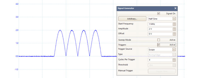
All units have a built-in function generator (sine, square, triangle, DC level, white noise, PRBS etc). As well as basic controls to set level, offset and frequency, more advanced controls allow you to sweep over a range of frequencies. Combined with the spectrum peak hold option this makes a powerful tool for testing amplifier and filter responses. Trigger tools allow one or more cycles of a waveform to be output when various conditions are met such as the scope triggering or a mask limit test failing. The PicoScope 3000 Series D models also include an arbitrary waveform generator. Waveforms can be created or edited using the built-in AWG editor, imported from oscilloscope traces, or loaded from a spreadsheet.
Advanced Digital triggers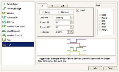
The majority of digital oscilloscopes sold today still use an analog trigger architecture based on comparators. This can cause time and amplitude errors that cannot always be calibrated out. The use of comparators often limits the trigger sensitivity at high bandwidths. In 1991 we pioneered the use of fully digital triggering using the actual digitized data. This technique reduces trigger errors and allows our oscilloscopes to trigger on the smallest signals, even at the full bandwidth. Trigger levels and hysteresis can be set with high precision and resolution. The reduced re-arm delay provided by digital triggering, together with segmented memory, allows the capture of events that happen in rapid sequence. At the fastest timebase, rapid triggering can capture a new waveform every 2 microseconds until the buffer is full. The mask limit testing function helps to detect waveforms that fail to meet your specifications. As well as the standard range of triggers found on all oscilloscopes, the PicoScope 3000 Series offers an industry-leading set of advanced triggers including pulse width, windowed and dropout triggers to help you capture the data you need. More information on advanced triggers > USB connectivity
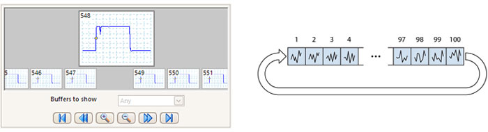
The USB connection not only allows high-speed data acquisition and transfer, but also makes printing, copying, saving, and emailing your data from the field quick and easy. USB powering removes the need to carry around a bulky external power supply, making the kit even more portable for the engineer on the move. PicoScope 3000 Series mixed signal oscilloscopes feature a SuperSpeed USB 3.0 connection, making the already-optimized process of data transfer and waveform update rates even faster. Further benefits of a USB 3.0 connection include faster saving of waveforms and faster gap-free continuous streaming of up to 125 MS/s when using the SDK, while the scope is still backward- compatible with older USB systems. High-end features as standardBuying a PicoScope is not like making a purchase from other oscilloscope companies, where optional extras considerably increase the price. With our scopes, high-end features such as serial decoding, mask limit testing, advanced math channels, segmented memory, and a signal generator are all included in the price. To protect your investment, both the PC software and firmware inside the scope can be updated. Pico Technology have a long history of providing new features for free through software downloads. We deliver on our promises of future enhancements year after year, unlike many other companies in the field. Users of our products reward us by becoming lifelong customers and frequently recommending us to their colleagues. 200MHz USB 3.0 oscilloscopes with 16 channel logic analyser100,000 waveforms per second PicoScope persistence modes allow you to collect thousands of waveforms per second in order to quickly spot glitches and observe jitter. New or more frequent data can be displayed in a brighter color or shade. Hardware acceleration (HAL3) allows waveform update rates of up to 100,000 per second outperforming all other PC oscilloscopes and many benchtop oscilloscopes costing considerably more. More information on color persistence modes >> Waveform buffer and navigatorEver spotted a glitch on a waveform, but by the time you’ve stopped the scope it has gone? With PicoScope you no longer need to worry about missing glitches or other transient events. PicoScope can store the last ten thousand waveforms in its circular waveform buffer. When the trace length is set to be shorter than the scope’s memory, PicoScope will automatically configure the memory as a circular buffer storing as many as ten thousand waveforms. The buffer navigator provides an efficient way of navigating and searching through waveforms effectively letting you turn back time. Tools such as mask limit testing can also be used to scan through each waveform in the buffer looking for anomalies.
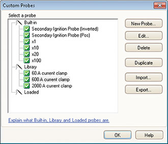
Custom probesThe custom probes feature allows you to correct for gain, attenuation, offsets and nonlinearities in special probes, or to convert to different units of measurement (such as current, power or temperature). You can save definitions to disk for later use. Definitions for standard Pico–supplied oscilloscope probes and current clamps are included. More information on custom probes >> Spectrum analyzer
With the click of a button you can display a spectrum plot of selected channels up to the full bandwidth of the oscilloscope. A full range of settings gives you control over the number of spectrum bands, window types, and display modes (instantaneous, average, or peak-hold). You can display multiple spectrum views with different channel selections and zoom factors, and place these alongside time-domain views of the same data. A comprehensive set of automatic frequency-domain measurements can be added to the display, including THD, THD N, SNR, SINAD and IMD. You can even use the AWG and spectrum mode together to perform swept scalar network analysis. More information on the PicoScope Spectrum analyser >> 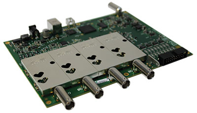 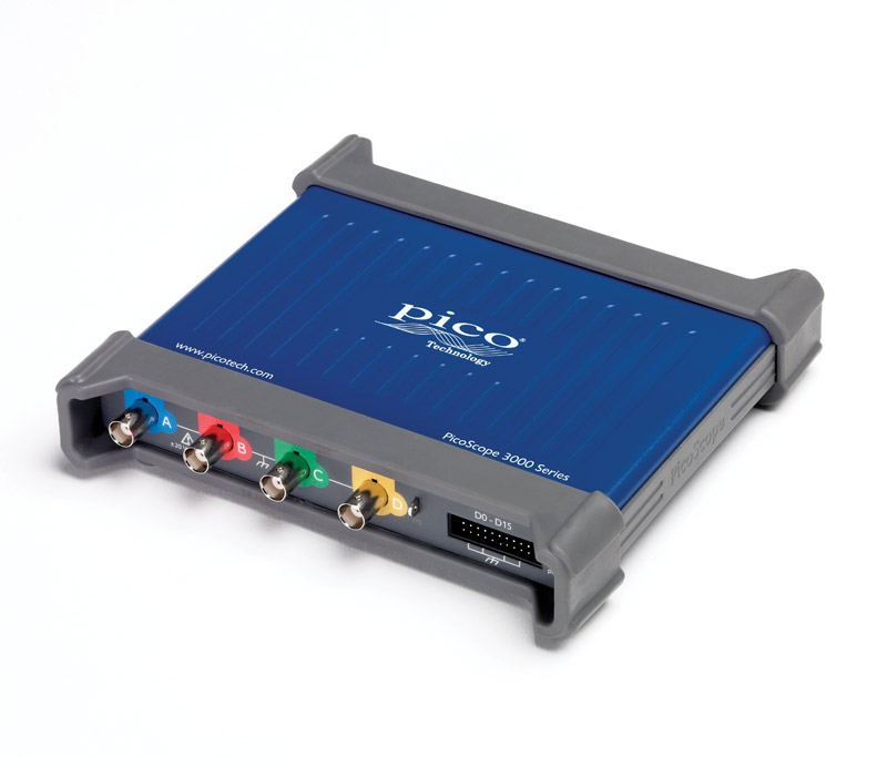
Signal integrityMost oscilloscopes are built down to a price. PicoScopes are built up to a specification. Careful front-end design and shielding reduces noise, crosstalk and harmonic distortion. Years of oscilloscope design experience can be seen in improved bandwidth flatness and low distortion. The result is simple: when you probe a circuit, you can trust in the waveform you see on the screen. PicoScope 3000 Series MSO & Non MSO oscilloscope specifications
* analog channels only
* analog channels only
PicoScope 3000 series oscilloscope softwareAdvanced displayThe PicoScope software dedicates almost all of the display area to the waveform. This ensures that the maximum amount of data is seen at once. The viewing area is much bigger and of a higher resolution than with a traditional benchtop scope. With a large display area available, you can also create a customizable split-screen display, and view multiple channels or different variants of the same signal at the same time. As the example below shows, the software can even show both oscilloscope and spectrum analyzer traces at once. Additionally, each waveform shown works with individual zoom, pan, and filter settings for ultimate flexibility. The PicoScope software can be controlled by mouse, touchscreen or by keyboard shortcuts.  Serial decoding / Protocol analysisThe PicoScope 3000 series include serial decoding capabilities as standard. The decoded data can be displayed in the format of your choice: In view, In Table, or both at once.
PicoScope can decode I²C, RS-232/UART, SPI, I²S, FlexRay, LIN and CAN bus data. Expect this list to grow over time with future free software upgrades. The number of different protocols that can be decoded at one time is limited only by the number of channels on your oscilloscope.
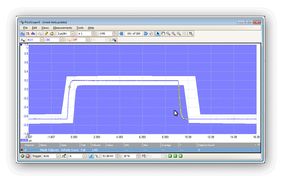
Mask limit testingMask limit testing allows you to compare live signals against known good signals, and is designed for production and debugging environments. Simply capture a known good signal, draw a mask around it, and then attach the system under test. PicoScope will capture any intermittent glitches and can show a failure count and other statistics in the Measurements window. Mask limit testing is available for both the oscilloscope and spectrum analyzer allowing you automate finding problems in both the time and frequency domain. The numerical and graphical mask editors can be used separately or in combination, allowing you to enter accurate mask specifications, modify existing masks, and import and export masks as files. More information on mask limit testing >>
Automatic measurementsPicoScope allows you to display a table of calculated measurements for troubleshooting and analysis. Using the built-in measurement statistics you can see the average, standard deviation, maximum and minimum of each measurement as well as the live value. You can add as many measurements as you need on each view. For information on the measurements available in scope and spectrum modes. More information on automatic measurements >>  Math channelsOn many oscilloscopes waveform maths just means simple calculations such as A B, with a PicoScope it means much, but much more. With PicoScope 6 you can select simple functions such as addition and inversion, or open the equation editor to create complex functions involving filters (low pass, high pass, band pass and band stop filters), trigonometry, exponentials, logarithms, statistics, integrals and derivatives.
 Waveform math also allows you to plot live signals alongside historic peak or averaged waveforms. You can also use math for example to graph the changing duty cycle or frequency of your signal. More information on math channels >> High-speed data acquisition and digitizerThe software development kit (SDK) allows you to write your own software and includes drivers for Microsoft Windows, Apple Mac (OS X) and Linux (including Raspberry Pi). Example code shows how to interface to third-party software packages such as Microsoft Excel, National Instruments LabVIEW and MathWorks MATLAB. The drivers support USB data streaming, a mode which captures gap-free continuous data over USB direct to the PC’s RAM or hard disk at rates of up to 125 MS/s and capture sizes limited only by available PC storage. Sampling rates in streaming mode are subject to PC specifications and application loading. Powerful tools provide endless optionsYour PicoScope is provided with many powerful tools to help you acquire and analyse waveforms. While these tools can be used on their own, the real power of PicoScope lies in the way they have been designed to work together. As an example the rapid trigger mode allows you to collect 10,000 waveforms in a few milliseconds with minimal dead time between them. Manually searching through these waveforms would be time consuming so just pick a waveform you are happy with and let the mask tools scan through for you. When done the measurements will tell you how many have failed and the buffer navigator allows you to hide the good waveforms and just display the problem ones. This video shows you how. Perhaps instead you want to plot changing duty cycle as a graph? How about outputting a waveform from the AWG and also automatically saving the waveform to disk when a trigger condition is met? With the power of PicoScope the possibilities are almost endless.
|
|||||||||||||||||||||||||||||||||||||||||||||||||||||||||||||||||||||||||||||||||||||||||||||||||||||||||||||||||||||||||||||||||||||||||||||||||||||||||||||||||||||||||||||||||||||||||||||||||||||||||||||||||||||||||||||||||||||||||||||||||||||||||||||||||||||||||||||||||||||||||||||||||||||||||||||||||||||||||||||||||||||||||||||||||||||||||||||||||||||||||||||||||||||||||||||||||||||||||||||||||||||||||||||||||||||||||||||||||||||||||||||||||||||||||||||||||||||||||||||||||||||||||||||||||||||||||||||||||||||||||||||||||||||||||||||||||||||||||||||||||||||||||||||||||||||||||||||||||||||||||||||||||||||||||||||||||||||||||||||||||||||||||||||||||||||||||||||||||||||||||||||||||||||||||||||||||||||||||||||||||||||||||||||||||||||||||||||||||||||||||||||||||||||||||||||||||||||||||||||||||||||||||||||||||||||||||||||||||||||||||||||||||||||||||||||||||||||||||||||||||||||||||||||||||||||||||||||||||||||||||||||||||||||||||||||||||||||||||||||||||||||||||||||||||||||||||||||||||||||||


| Product | Description | Price |
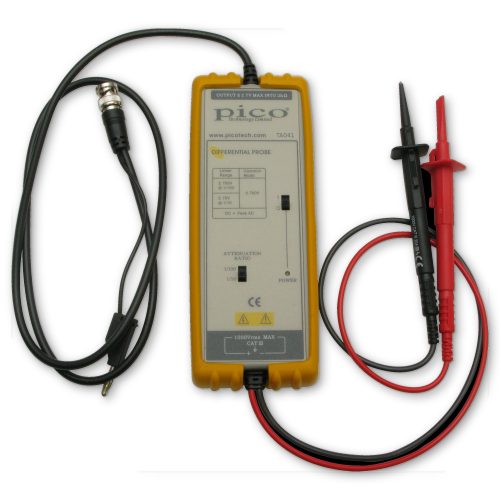 |
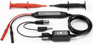
25 MHz 700 V differential oscilloscope probe 10:1/100:1 TA041 |
|
|
25 MHz 1400 V differential oscilloscope probe 20:1/200:1 TA057 |
|
 |
50 MHz 70 V differential oscilloscope probe 10:1 TA058 |
|
 |
70 MHz 7000 V differential oscilloscope probe 100:1/1000:1 TA044 |
|
|
100 MHz 700 V differential oscilloscope probe 10:1/100:1 TA043 |
|
|
100 MHz 1400 V differential oscilloscope probe 100:1/1000:1 TA042 |
High bandwidth active probes
This range includes high-voltage probes that extend the input range of your scope, and high-frequency probes that boost its input impedance for more accurate measurements.
All active probes require a power supply or batteries. Our battery-powered probes are supplied complete with batteries, while optional AC adaptors are available for the externally powered types. Read our application note: Choosing the right Pico Technology active differential probe.
For making differential measurements whether measuring millivolts or upto 1000V CAT III consider also our PicoScope 4444 differential input oscilloscope
| Product | Description | Price |
 |
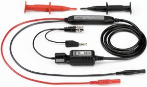
200 MHz 20 V differential oscilloscope probe 10:1 TA045 |
Current probes (clamps)
Clamp-on current probes or “current clamps” enable you to measure currents without breaking the electrical circuit. Current clamps are designed with jaws that can be opened, placed around the conductor and clamped shut to form a magnetic loop around the conductor.
Current clamps offer a safe, cost-effective, simple and accurate way to take current measurements.
Our range of current clamps can be used with PicoScope Oscilloscopes and PicoLog Data Loggers, as well all major brands of oscilloscopes and multimeters
| Product | Description | Price |
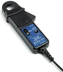 |
30 A AC/DC precision current probe, BNC connector TA189 |
|
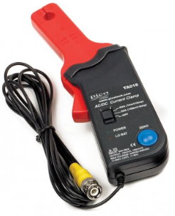 |
60 A AC/DC current probe, BNC connecto PP264 (TA018) |
|
 |
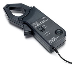
200 A / 2000 A AC/DC current probe, BNC connector TA167 |
|
 |
600 A AC/DC current probe, BNC connector TA019 |
Accelerometers
We supply single-axis and three-axis accelerometers that connect to an oscilloscope for measuring noise and vibration.| Product | Description | Price |
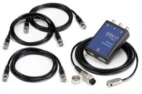 |
Three-axis accelerometer and oscilloscope interface The PP877 is a MEMS-based three-axis accelerometer and oscilloscope interface. It is supplied with 3 short BNC to BNC cables which plug directly into any PicoScope oscilloscope with 3 or more analog channels. High-resolution oscilloscopes such as the PicoScope 4000 Series are recommended to take advantage of their increased sensitivity.
|
BNC terminators and leads
All our BNC terminators, attenuators, leads and adaptors are compatible with 50 Ω BNC connectors.Link to BNC Terminators and Leads>>>>>
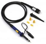
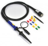
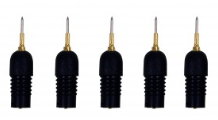
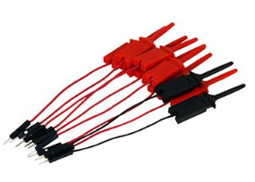
Clips, leads and 4 mm probes
From gator/croc clips to acupuncture probes, here you will find a variety of popular accessories for use with test and measurement equipment.Our test clips are suitable for general-purpose test and measurement as well as for automotive diagnostics applications. The test clips are designed for use with our range of test leads.
Link to our Clips, leads and 4mm Probes >>>>
Miscellaneous
| Product | Description | Price |
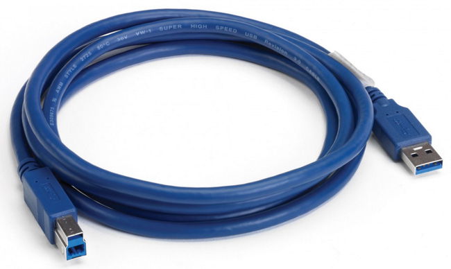 |
USB 3.0 cable, 1.8 m TA155 |
|
 |
Hard carry case – medium PP969 Recommended |
|
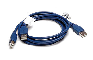 |
USB 2.0 Y-cable, 1.8 m TA146 |
|
 |
5 V AC power adaptor PS011 |
Calibration services
Calibration services>>>>>>
PicoScope 3200D Brochure
PicoScope 3200A & B Brochure [This unit has been replaced by the D Series]
Order your Pico 3000 Series MSO here
|
3203D MSO (PP956) bandwidth (MHz): 50
|
3204D MSO (PP931)
|
|
3205D MSO (PP932)
|
3206D MSO (PP933)
|
|
3403D MSO (PP957)
|
3404D MSO (PP934)
|
|
3405D MSO (PP935)
|
3406D MSO (PP936)
|
Order your Non MSO 3000 Series Scope here
|
3203D [PP958] |
3204D [PP959] |
|
3205D [PP960] |
3206D [PP961] |
|
3403D [PP962] |
3404D [PP963] |
|
3405D [PP964] |
3406D [PP965] |