|
To install and use the software:
1. Install Logic Combine Software
2. In the Logic Trace Software, trace the object in sections, and save the files as .PLN Logic Trace files
3. Start the Logic Trace Software and setup the number of sections to be combined
4. Load the .PLN files
5. Define how the sections are to be combined
6. Combine the sections and create a large DXF file
Trace the Sections
1. The sections are traced (digitized) in the Logic Trace software and saved as .PLN files. Tracing must be done in a counter-clockwise direction and stopped at each edge.
2. First, on the pattern to be traced in pencil mark the point where one section will start and the next section start. This will be the stopping and starting points for each trace. For example consider the following template that will need to be traced in three sections.
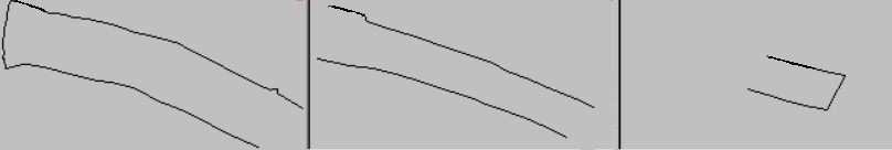
On the pattern in pencil (or tape) mark point 1 where digitizing will start and end, point 2 which is the end of the trace in the left section and the start of the trace in the middle section, point 3 which is the end of the trace in the middle section and the start of the trace in the right section, point 4 which is the end of the trace in the right section and the start of the trace in the middle section, and point 5 which is the end of the trace in the middle section and the start of the trace in the left section.

2. Place the left section of the pattern on the digitizing tablet and in the Logic Trace software trace from pt 1 to pt 2, click done, click start to trace another outline, and trace from point 5 back to point 1, click done. Remember to trace in a counter-clockwise direction. When finished, click File-Save As, name the file such as LEFT aand the program creates the LEFT.PLN file. The PLN files are the Logic Group digitized files.
3. If your template has a middle section, move the template so that the middle section is on the digitizing tablet. In the Logic Trace software, go to File New to restart the digitizing. Trace from pt 2 (it should be marked on the template in pencil or tape), to pt 3, click done, click start for another trace, trace from pt 4 to pt 5. Click Done, click File Save As and create the file MIDDLE.PLN.
5. Move the pattern so the right section is on the digitizer, click File New to restart, and trace from pt 3 to pt 4, click done, click File Save As and save as file RIGHT.PLN.
Setup Sections
1. Start the Logic Combine program, click the Windows Start button, Programs, The Logic Group, Logic Combine DXF, Logic Combine DXF.
2. Specify how many sections there are in the X and Y direction:
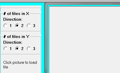
2. There can be up to 3 sections in each of the x and y directions with the default being two in each.
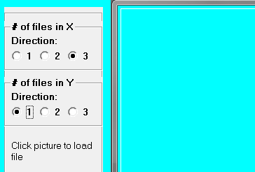
3. In the example shown previously there is three sections in the x direction and one section in the y direction.
Load .PLN Files
1. After setting up how many sections are in the x and y direction, the .PLN files must be loaded into the Logic Combine Software.
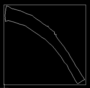
2. For each section, using the computer mouse click the section on the screen. A Load File window will pop up, change the folder to the file folder and click the file name, for example LEFT.PLN. The image will be displayed on the screen.
3. Repeat for all sections
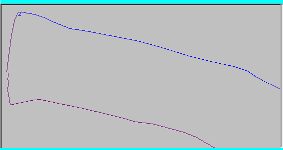
4. The software will number each trace on the screen:
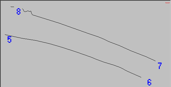
For example it has numbered the first trace in the middle section starting at point 5 and ending at point 6 and the second trace starting at point 7 and ending at point 8. We will need these points in the next step when we build the combined trace.
Define the Trace Combinations
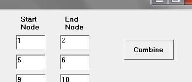
1. On the left menu, click the Combine button and the Combine DXF window is displayed:
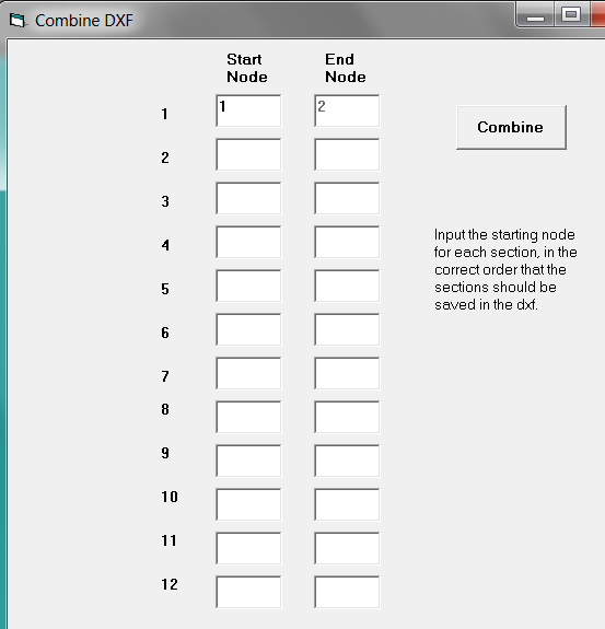
2. In this window, we build the outline of the pattern starting the first trace in the left section. We do not need to input the End Node (point) the program automatically adds it.
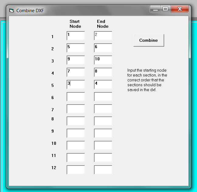
3. For our pattern with the three sections, the first trace goues from node 1 to 2 (in the left section), node 5 to 6 (in the middle section), node 9 to 10 (in the right section), node 7 to 8 (in the middle section) and node 3 to 3 in the left section).
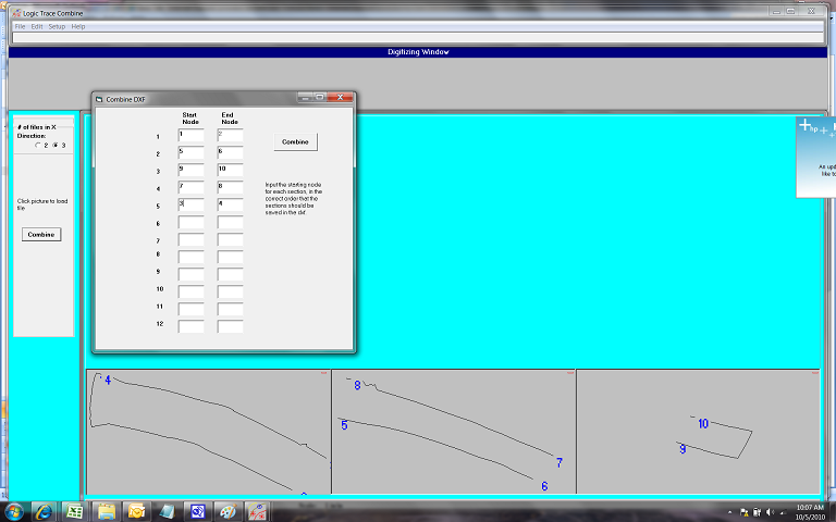
4. The program does display both the sections and combine window together to help with defininf the final trace (we have reduced the size here):
4. Inputting the values from step 3 in the Combine DXF window we build the trace:
Combine and Create DXF
1. Click the Combine Button in the Combine DXF window to combine the sections and create the DXF file
2. The Logic Combine software will combine the sections as defined and create a file COMBINE.DXF.

3. Load the combined dxf file into your cnc, cad, or cutting software.
|