


|
|
|||
| Log In | |||
|
| |||
|
| |||
| |||
| |||


Data Acquisition ![]() 6 GHz VNA
6 GHz VNA
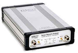
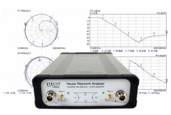
PicoVNA 6 or 8.5GHz Vector Network Analyzer
Making vector network analysis accessible
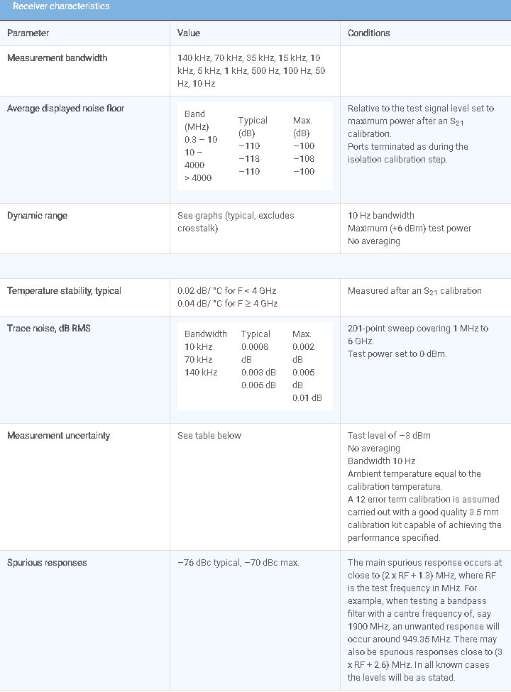
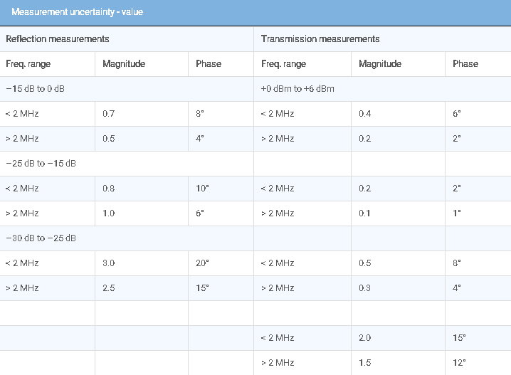
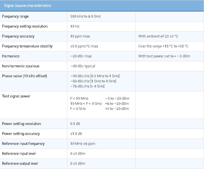
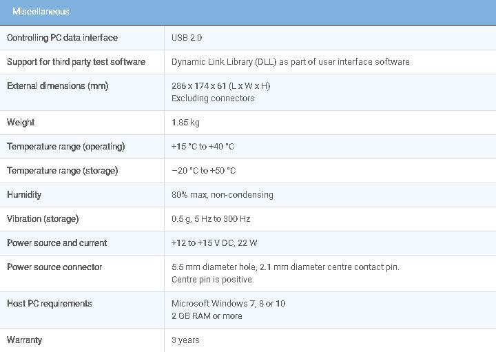
Today's microwave measuring instruments need to be straightforward, accurate, portable and affordable. No longer restricted to specialists, they are now used by scientists, educators, surveyors, inspectors, engineers and technicians in radio and gigabit data applications. Now Pico Technology has applied its expertise in microwave sampling oscilloscopes and time domain transmission and reflectometry to bring you a USB vector network analyzer. The PicoVNA 106 is a professional USB-controlled, laboratory grade vector network instrument of unprecedented performance, portability and affordability. Despite its small size and low cost, the instrument boasts a ‘Quad RX’ four-receiver architecture to eliminate the uncorrectable errors, delays and fragility of three-receiver designs with internal transfer switches. The PicoVNA 106 offers exceptional dynamic range of 118 dB and only 0.005 dB RMS trace noise at its maximum operating bandwidth of 140 kHz. It can also gather all four s-parameters at every frequency point in just 190 µs; in other words a 500 point 2-port .s2p Touchstone file in less than one tenth of a second. The cost is so low that the PicoVNA 106 could even be used as a cost-effective high-dynamic-range scalar network analyzer! It's affordable in the classroom, small business and even amateur workshop, yet capable in the microwave expert's laboratory. Vector network analysis everywhere
PicoVNA 106 features
|
||||||||||||||||||||||||||||||||||||||||||||||||||||||||||||||||||||||||||||||||

| Resource | Language | Version | Size | Updated |
| Data Sheets: | ||||
| PicoVNA 106 6 or 8.5 Ghz GHz Vector Network Analyzer Data Sheet | English | 5 | 2 MB | November 01 2020 |
| User's Guides: | ||||
| PicoVNA Vector Network Analyzer User’s Guide | English | 1 | 4 MB | July 21 2017 |
| Programmer's Guides: | ||||
| PicoVNA Vector Network Analyzer Programmer’s Guide | English | 1 | 684 KB | October 11 2017 |
| Quick Start Guides: | ||||
| PicoVNA 106 6 GHz Vector Network Analyzer Quick Start Guide | English | 2 | 517 KB | August 08 2017 |
| Technical Data: | ||||
| PicoVNA 106 sample calibration certificate | English | 2 | 1 MB | September 20 2017 |
| Declarations: | ||||
| PicoVNA 106 Vector Network Analyzer Statement of Volatility | English | 2 | 110 KB | November 13 2017 |
| PicoVNA 106 EU Declaration of Conformity | English | 1 | 749 KB | October 18 2017 |
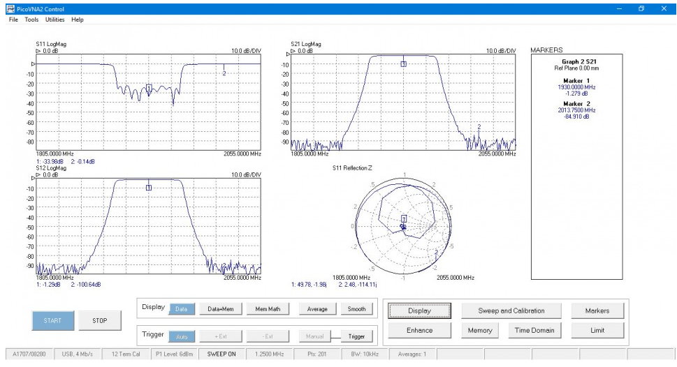
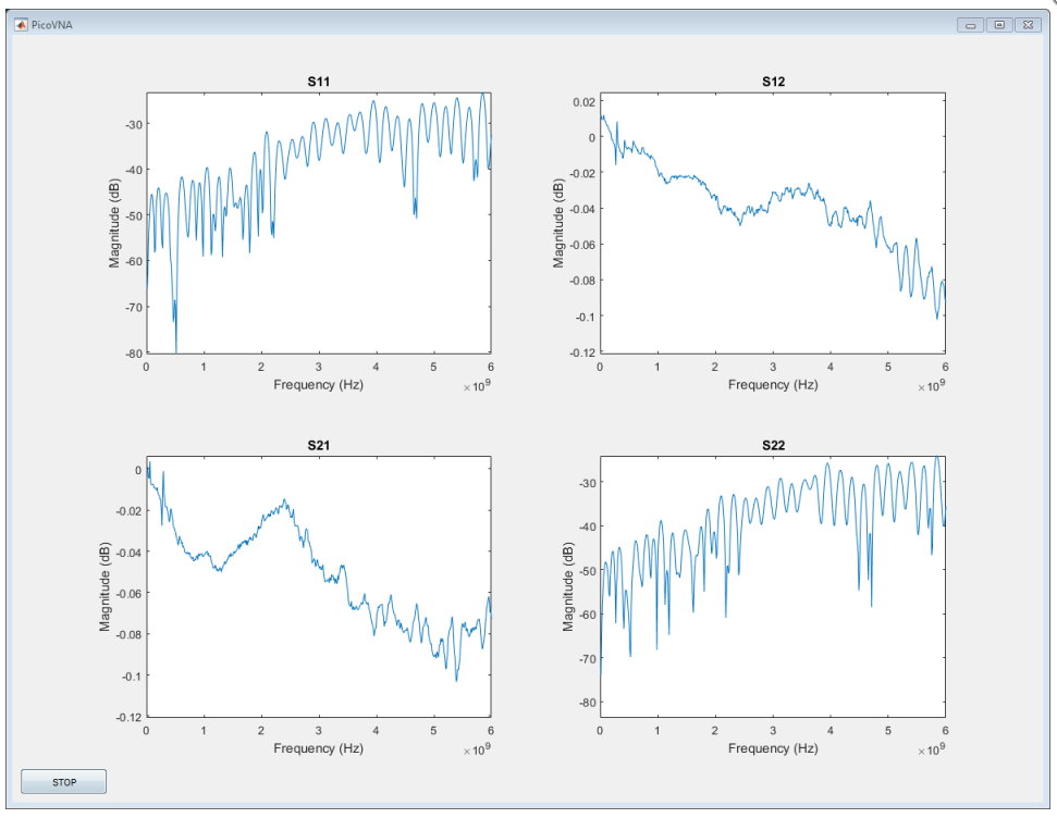
PicoVNA 2 software PicoVNA 2 presents standard VNA measurement and calibration simply, intuitively and with efficient usage at its heart. The software offers a comprehensive range of measurements and plot formats in its one, two or four user-configurable measurement channels. All the standard vector network analyzer functions can be seen at a glance.
Supported calibrations
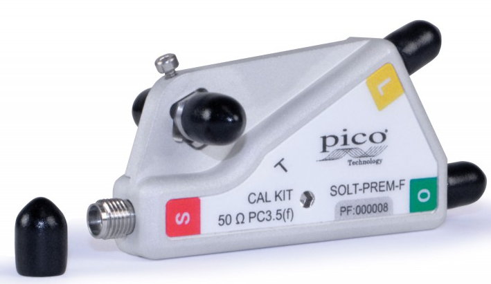
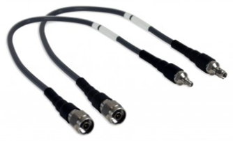
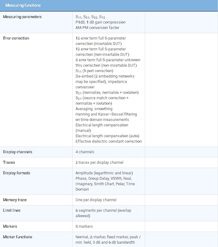
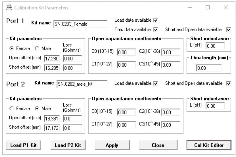
The PicoVNA 2 software supports a comprehensive range of calibration modes to address single or dual-port workload with male, female or mixed gender interfaces, all with best achievable accuracy (least uncertainty). In some instances only a single calibration kit may be required. As you would expect, the Pico calibration kits are individually serial-numbered and supplied with S-parameter data. This standard-form data is a traceable and accurate record of measured errors for the calibration kit. It can be loaded into the software, which will correct for these errors and those of the instrument during a calibration. Alternatively, you can use a third-party calibration kit and its data, or you can enter its electrical length, parasitic values and polynomial coefficients into the software if these are supplied rather than a profile data set. As for any vector network analyzer, for best accuracy a calibration is performed before a measurement with the same sweep span and frequency steps as the measurement. If, however, a change of sweep settings is necessary for a measurement, the PicoVNA 2 software will for convenience interpolate its corrections to the new sweep settings. An enhanced isolation calibration setting is available for optimum dynamic range when using resolution bandwidths below around 1 kHz.
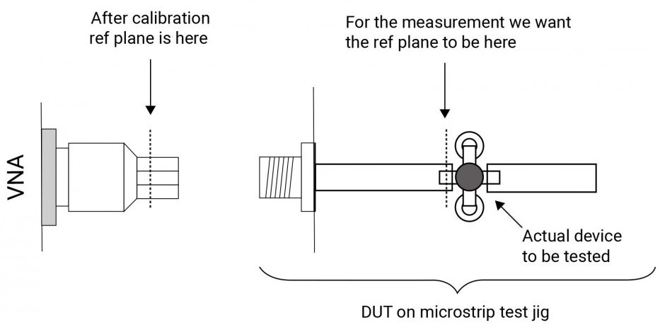
Reference plane extension
Reference plane extension (offset) allows you to shift the measurement reference plane away from the point established during calibration. This is useful in removing the path length of assumed ideal interconnecting , connectors cables or microstrip lines from measurements. The PicoVNA 2 software allows independent reference plane extensions on each of the measurement parameters (S11, S22, S12 or S21), either as an automatic re-reference or by manual entry. Independent extensions allow, for example, different extensions on the two ports for S11 and S22 and then thru-line normalization for S21 and S12 transmission comparison with equivalent length thru-line.
De-embedding embedded port interfaces
When it is unsafe to assume the above ideal interconnecting connectors cables or microstrip lines; for example to achieve greater accuracy or to remove known imperfections in a test setup, we can choose instead to de-embed the interface networks on each measurement port. The PicoVNA 2 software simply requires a full Touchstone .s2p file for the embedded interfacing network on each port. Likewise, defined networks can be embedded into the measurement to achieve a desired simulated measurement. As for a calibration, best accuracy will be achieved when the embedding network is defined at the same frequency points as the intended measurement. Unusually for a vector network analyzer, the PicoVNA 2 software will interpolate where necessary and possible.
Z0 impedance reference
System measurement impedance (default 50 Ω) can be mathematically converted to any value between 10 Ω and 200 Ω. The PicoVNA 2 software also supports the use of external matching pads and calibration in the new impedance using a calibration kit of that impedance.
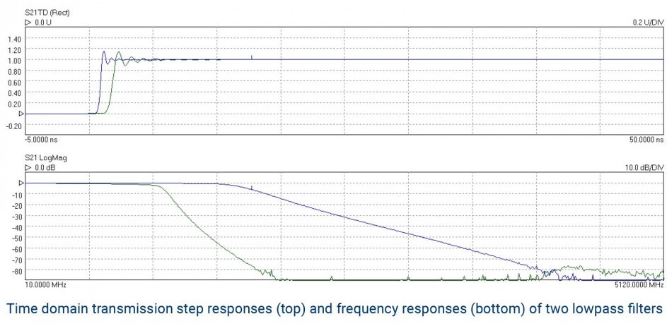
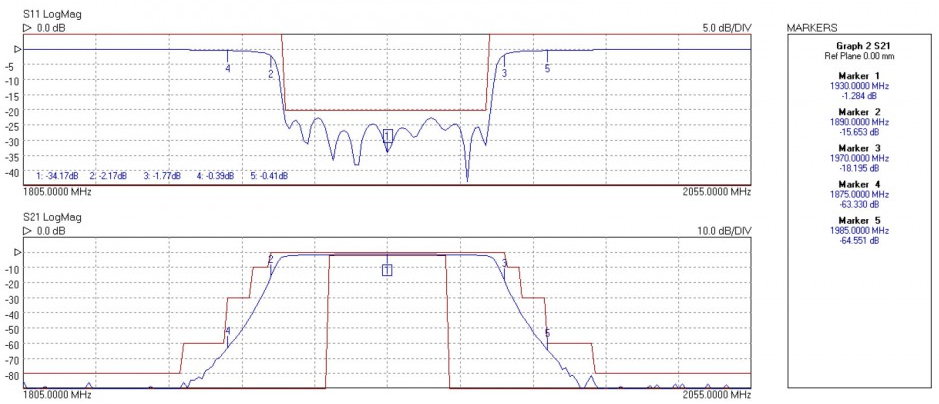
Time domain transmission and reflectometry measurements
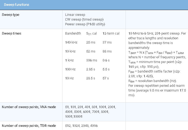
Time domain reflectometry is useful in the measurement of a transmission line; in particular the distance-to-fault location of any discontinuity due to connectors, damage or design error. To achieve this, the PicoVNA 2 software determines from its frequency domain measurements the time domain response to a step input. Using a sweep of harmonically related frequencies, an inverse fast Fourier transform of reflected frequency data (S11) gives the impulse response in the time domain. The impulse response is then integrated to give the step response. Reflected components of the step, occurring at measurable delays after excitation, indicate the type of discontinuity and (assuming a known velocity of propagation) the distance from the calibration plane. A similar technique is used to derive a TDT (time domain transmission) signal from the transmitted signal data (S21). This can be used to measure the pulse response or transition time of amplifiers, filters and other networks. The PicoVNA 2 software supports Hanning and Kaiser–Bessel lowpass filtering on its time-domain IFFT conversions, preserving magnitude and phase, and achieving best resolution. A DC-coupled DUT is essential to the method.
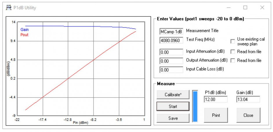
P1dB utility
The 1 dB gain compression point of amplifiers and other active devices can be measured using a power sweep, either at a test frequency or over a sweep of test frequencies. The VNA determines the small-signal gain of the amplifier at low input power, and then increases the power and notes the point at which the gain has fallen by 1 dB. This utility uses a second-order curve fit to determine interpolated 1 dB compression points.
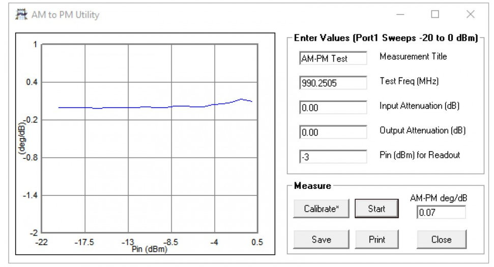
AM to PM conversion utility
AM to PM conversion is a form of signal distortion where changes in the amplitude of a signal produce corresponding changes in the phase of the signal. This type of distortion can have serious impact in digital modulation schemes for which amplitude varies and phase accuracy is important.
Limit lines testing
The limit lines facility allows six segments to be defined for each displayed plot. These can be extended to 11 segments using an overlapping technique. Visual and audible alarms can be given when a limit line is crossed. All plot formats except Smith chart and polar support limit testing. Peak hold functions are also available.
Example code
The PicoVNA 2 software provides an ActiveX server, allowing you to write your own software to communicate with the PicoVNA Vector Network Analyzer on Microsoft Windows platforms.
Example code is available via our GitHub organization page, including a toolbox for use with MathWorks MATLAB.
ORDER ONLINE TODAY:
| Pico VNA 106 Order the PQ111 5Ghz Unit Today |
Pico VNA 108 Order the PQ112 8.5 Ghz Unit Today |