


Introduction
For many engineers, choosing a new oscilloscope can be daunting — there are hundreds of different models to choose from with widely varying costs and specifications. This article guides you through the maze of considerations and will hopefully help you avoid making what could prove to be an expensive mistake.
By Alan Tong, Technical Director, Pico Technology.
First Things First
The first step in choosing an oscilloscope is not to look at adverts or scope specifications, rather it is to invest some time thinking about what you will use it for and where.
- Where will you use the scope (on the bench, at a customer's site, under the hood of a car)?
- How many signals do you need to measure at once?
- What are the maximum and minimum amplitudes of signals that you need to measure?
- What is the highest frequency of signal you need to measure?
- Are your signals repetitive or single shot?
- Do you need to view signals in the frequency domain (spectrum analysis) as well as the time domain?
Armed with the above knowledge, you can begin to consider what oscilloscope will be best for your applications.
Analog vs Digital
The focus of this article is on Digital Storage Oscilloscopes (DSOs) as they represent the majority of new oscilloscopes purchased today. Before describing what to look for in an digital oscilloscope, it is necessary to begin by at least touching on analog.
Most electronics engineers will have used an analog scope at some time and will be familiar with its layout and operation. In fact, many people purchasing oscilloscopes today are replacing analog with digital.
Although there are still some engineers who love the look-and-feel (let alone the warmth) of analog scopes, they have few, if any, features that cannot be surpassed by a DSO.
If you are still tempted by an analog scope you will find your choice limited. Only a few manufacturers still make analog scopes; some of the models still on sale are based on rather old technology and often have very limited performance.
Buying a second hand analog scope may initially seem like good economic sense but, before doing so, check for the availability of spares, as high repair costs can make the purchase a false economy.
There are other criteria that have added weight to the analogue vs digital debate. DSOs:
- are small and portable
- have the highest bandwidths
- have single shot ability
- have colour displays
- provide on-screen measurements
- have simple user interface
- provide storage and printing
Modern DSOs, with their PC connectivity, can also be fully integrated into Automatic Test Equipment (ATE) systems. In addition, the DSO is often used as the front-end of a high speed data acquisition system, making the cost per channel much more economically viable.
Bandwidth
The first feature to consider is bandwidth. This can be defined as the maximum frequency of signal that can pass through the front-end amplifiers. It therefore follows that the analogue bandwidth of your scope must be higher than the maximum frequency that you wish to measure (real time).
Bandwidth alone is not enough to ensure that a DSO can accurately capture a high frequency signal. The goal of scope manufacturers is to achieve a specific type of frequency response with their designs. This response is known as the Maximally Flat Envelope Delay (MFED). A frequency response of this type delivers excellent pulse fidelity with minimum overshoot, undershoot and ringing. However, since a DSO is composed of amplifiers, attenuators, ADCs, interconnects, and relays, MFED response is a goal that can only be approached, and never met completely.
It is worth noting that most scope manufacturers define the bandwidth as the frequency at which a sine wave input signal will be attenuated to 71% of its true amplitude (-3dB point). Or, to put it another way, they allow the displayed trace to be 29% in error of the input before calling it a day.
Remember also that, if your input signal is not a pure sine wave, it will contain higher frequency harmonics. For example, a 20MHz pure square wave viewed on a 20MHz bandwidth scope will be displayed as an attenuated and distorted waveform. As a rule of thumb, try to purchase a scope with a bandwidth five times higher than the maximum frequency signal you wish to measure. Unfortunately, high bandwidth scopes are expensive, so you may have to compromise here.
On some scopes, the quoted bandwidth is not available on all voltage ranges, so check the data sheet carefully.
Sample Rate
With analog scopes life was simple: you just selected the bandwidth that you required. For digital scopes, sampling rate and memory depth are equally important. For DSO's, the sampling rate is usually specified in mega samples per second (MS/s) or giga samples per second (GS/s). The Nyquist criterion states that the sampling rate must be at least twice the maximum frequency that you want to measure: for a spectrum analyser this may be true, but for a scope you require at least 5 samples to accurately reconstruct a waveform.
Most scopes have two different sampling rates (modes) depending on the signal being measured: real time and equivalent time sampling (ETS) - often called repetitive sampling. However, ETS only works if the signal you are measuring is stable and repetitive, since this mode works by building up the waveform from successive acquisitions.
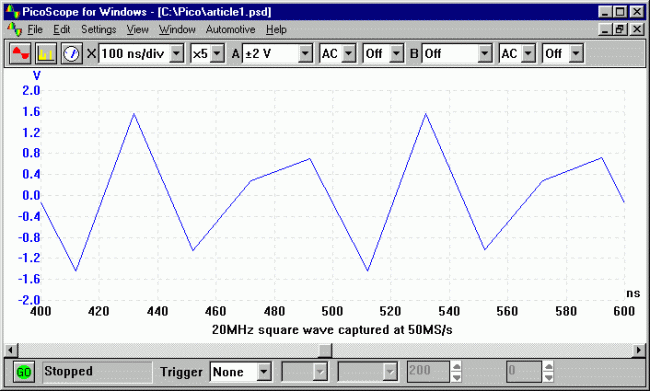
figure 1a: 20MHZ square wave captured with a sampling rate of 50MS/s.
For example the Pico Technology 12-bit ADC-212/100 will sample at 100MS/s real-time or, for repetitive waveforms, at 5GS/s. Figure 1a shows a 20MHz square wave captured with a sampling rate of 50MS/s - almost unrecognizable compared to Figure 1b, the same wave captured at 5GS/s. Now, 5GS/s sounds great, but remember that if the signal is a transient or changing (say a video waveform) then ETS will not work and you will have to rely on the real time (single shot) bandwidth, which is typically much lower.
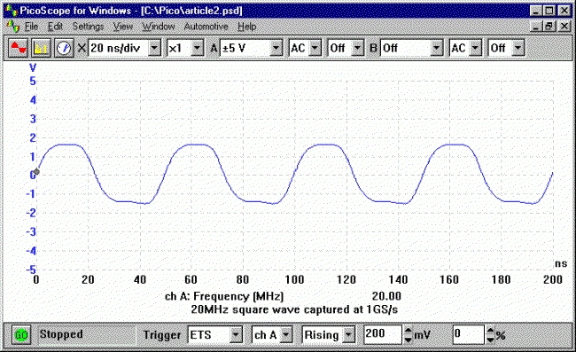
figure 1b: 20MHZ square wave captured at 1GS/s.
A word of advice: scope manufacturers like to highlight the best sounding specification, so you may need to look carefully at the specifications to work out if a quoted sampling rate applies to all signals, or to only repetitive ones. You may find that the scope you are planning to purchase is not 'fit-for-purpose'.
Some scopes have different sampling rates, depending on the number of channels in use. Typically, the sampling rate in single channel mode is twice that in dual channel mode: once again, check the specifications.
Memory Depth
Memory depth is perhaps the least understood aspect of a DSO which is a shame because it is one of the most important.
DSOs store captured samples in a buffer memory, so, for a given sampling rate, the size of the buffer memory determines how long it can capture a signal for before the memory is full.
The relationship between sampling rate and memory depth is important; a scope with a high sampling rate but small memory will only be able to use its full sampling rate on the top few timebases. Figure 2a shows 200ms of a video waveform captured using 1K of buffer memory. The 1K buffer memory limits the sampling rate to 5MS/s (1K / 200ms) even though the scope is capable of sampling at 100MS/s.
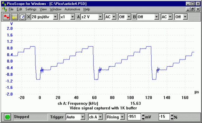
figure 2a: 200uS of a video wave captured with a 1K buffer memory.
At first glance, this seems to have captured the waveform satisfactorily. However, the limitation of the small buffer memory is revealed when the waveform is expanded to 'zoom in' on the colour burst signal (Figure 2b). The colour burst (oscillations at the base of the 'steps') lasts about 5ms so is only represented by 25 points in memory fine for normal view but, when we zoom in, those few points are used to fill the screen.
Figure 2c shows the same colour burst section of the video waveform but this time captured on a scope with a 128K buffer memory. We have more than 3000 points available to represent the colour burst section and the difference is noticeable.
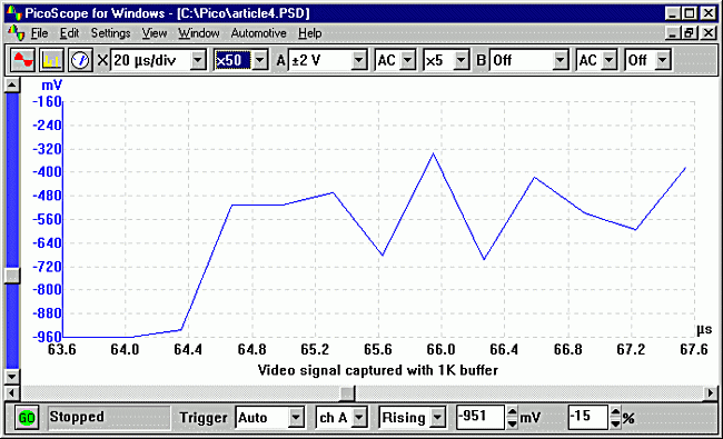
figure 2b: The limitation of the small buffer memory is revealed when the waveform is expanded to display the colour burst signal.
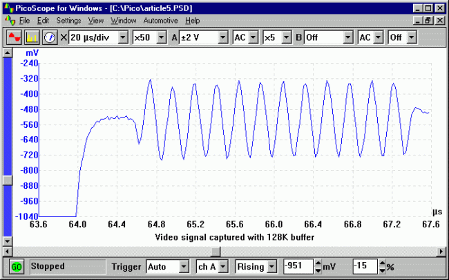
figure 2c: shows the same waveform, this time using a 128kB buffer memory.
Real World Example
To make sense of the relationship between bandwidth, sampling rate and memory depth, it makes sense to consider a real world example. Consider trying to capture one frame of USB (1.1) data. A frame of data lasts 1ms and has serial data transmitted at 12MBPS. To simplify our analysis, we can assume that we have to capture a 12MHz square wave for 1ms.
- Bandwidth - to measure the 12MHz signal, we need an absolute minimum of 12MHz, however this will give a very distorted signal so a scope with at least 50MHz bandwidth would be sensible.
- Sampling rate - to reconstruct the 12MHz signal, we need around 5 points per waveform, so a minimum sampling rate of 60MS/s is required.
- Memory depth - to capture data at 60MS/s for 1ms requires a minimum memory depth of 60,000 samples.
Resolution and Accuracy
In digital electronics, a signal change of 1% is usually no problem, but in audio electronics, 0.1% distortion or noise can be a disaster. Most modern DSOs are optimized for use with fast digital signals and only offer 8 bit resolution (8 bit ADC), so can detect at best a 0.4% signal change (see table).
With 8 bits, the voltage range is divided up into 256 vertical steps (2^8 = 256). With a /-1V range selected, this corresponds to around 8mV per step. This may be adequate for viewing digital signals but leave something to be desired for viewing analog signals, especially when using the spectrum analyser function (if it has one).
For applications such as audio, noise, vibration and monitoring sensors (temperature, current, pressure) an 8 bit oscilloscope is often not suitable and you should consider 12 or 16 bit alternatives.
As for a DSO's accuracy, it is not usually regarded as too important. You can make measurements within a few percent (most 8 bit DSO's quote 3% to 5% DC accuracy) but for more accurate measurements you should reach for a multimeter.
With a higher resolution oscilloscope, more accurate measurements are possible (1% or better) so - no need for the meter!
Oscilloscopes with both a high resolution (12 bits or more) and a high DC accuracy are sometimes referred to as precision oscilloscopes - see our application note on High resolution oscilloscopes and FFT spectrum analysers.
Triggering Capabilities
A scope's trigger function synchronizes the horizontal sweep at the correct point of its signal: this is essential for clear signal characterization. Trigger controls allow you to stabilize repetitive waveforms and capture single-shot waveforms. Depending on the type of signals being investigated, it is worth looking at the trigger options offered by a manufacturer. All digital scopes offer the same basic trigger options (source, level, slope, pre/post trigger) but differ in the more advanced trigger functions. Whether or not the more advanced trigger functions will be useful again depends on the signals being measured. Pulse triggers are useful for digital signals, and an automatic save to disk/memory option can be a great help when tracking down intermittent faults.
Some application specific triggers (disk drive testing, for example) are often available as cost extras and are installed as a software or firmware upgrade. If you are likely to use one of these 'cost extras', don't be afraid to negotiate with the vendor. It is not unusual for such 'optional extras' to be thrown in free of charge to clinch the deal.
Input Ranges & Probes
A typical scope will offer selectable full scale input ranges from -50mV to -50V. As higher voltages can be measured using 10:1 and 100:1 attenuating oscilloscope probes, the important thing here is to check that the scope has a small enough voltage range for the signals that you want to measure. If you regularly measure small signals (less than 50mV), consider buying a scope with a 12 or 16 bit resolution. A 16 bit scope has 256 times the vertical resolution of an 8 bit scope, making it possible to 'zoom in' on millivolt and microvolt level signals.
Check that the scope probes you plan to use match - or better - the bandwidth of the scope. Some manufacturers make cost savings by supplying sub-standard probes with the scope and only supply the higher bandwidth probes, which are needed to get the best from the scope, as optional extras. Most scope probes can be switched between 1:1 and 10:1 attenuation. Wherever possible, use the 10:1 setting as this minimizes loading on the circuit under test and increases the overload protection should you accidentally connect to a high voltage.
For very high speed signals (>200MHz), passive probes begin to run into problems caused by the capacitance of the cable going back to the scope. This can be solved by investing in an active FET probe which places a buffer amplifier in the probe tip. For measuring high voltages, for example >100V, mains and 3 phase voltages, the safest option is to use a differential isolating oscilloscope probe.
Form Factor
DSOs broadly fall into three categories: traditional bench-top, hand-held, and PC-based.
A purpose built bench top digital scope will usually have the highest performance, and that will be reflected in the cost. Features such as FFT spectrum analysis, PC interfaces, disk drives and printers all tend to be expensive optional extras.
Hand-held oscilloscopes have obvious advantages for an engineer on the move, but beware of poor displays (difficult to read in sunlight) and short battery life. For a given performance level they also tend to be the most expensive option.
PC based oscilloscopes are growing in popularity as they offer a considerable cost saving over their benchtop equivalents. The reason for the cost saving is obvious; by using the mass produced PC already sitting on your desk, you end up with a large colour display, fast processor, disk drives and keyboard effectively for free. The ability to export data to word processors and spreadsheets with a couple of mouse clicks is also a big advantage.
PC based scopes come in two varieties: external and internal. Internal PC based scopes usually come in PCI format plug in cards. In theory, these should be the lowest cost option but this does not always prove to be true. The main disadvantage of PC cards is noise - the inside of a PC can be a very noisy electrical environment and some cards do suffer. Another issue is portability; oscilloscopes based on PC cards are tied to being used with one desktop PC.
External PC based oscilloscopes take the form of a small box that connects to the PC via either the USB or the parallel port. By keeping all the analog electronics outside the PC, the noise problem is avoided. A second advantage of external PC-based scopes is portability - they can be used with either desktop or laptop PCs;
Summing Up
Like the dinosaur, the analog scope has really had its day. The cost and performance arguments have made sure that the DSO is here to stay. It only remains to decide which type to buy.
When choosing between different scopes, check the following:
- Try before you buy - and do not be afraid to compare different scopes from different manufacturers. If a vendor will not offer a 'your money back if you are not satisfied' guarantee, then you are better off not dealing with them.
- For higher cost scopes, get demos and make sure the demos are done with the actual signals you want to measure, not just signals that show the scope in a good light.
- When buying any scope, ask about upgrades and check what is included in the cost. For PC-based scopes make sure the software is included and ask if you will have to pay for software upgrades. For bench top scopes check the cost of cables and software to connect to PCs/Printers - it can add 50% to the total cost.
- Check the length of warranty. If your unit fails in use, will the vendor lend another whilst it is being repaired?
- Finally, look on the internet for independent reviews of oscilloscopes. A search for 'oscilloscope review' on google.com is a good starting point.
In summary, and in order of priority, It is Bandwidth, Sampling rate (Real-time and/or Equivalent time) and then Memory depth. Note: bandwidth and sampling rate are not upgrade options on most DSOs, so once you've paid anything up to $60,000 you are stuck with your choice.