


|
|
|||
| Log In | |||
|
| |||
|
| |||
| |||
| |||


Overview
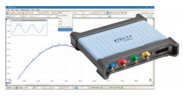
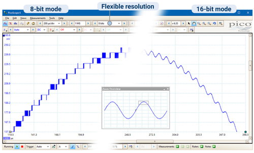
Flexible Resolution USB Oscilloscope
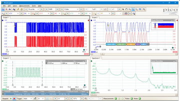
Today’s electronic designs employ a wide range of signal types: analog, digital, serial (both high- and low-speed), parallel, audio, video, power distribution and so on. All need to be debugged, measured and validated to ensure that the device under test is functioning correctly and within specification. What is FlexRes?
|
|||||||||||||||||||||||||||||||||||||||||||||||||||||||||||||||||||||||||||||||||||||||||||||||||||||||||||||||||||||||||||||||||||||||||||||||||||||||||||||||||||||||||||||||||||||||||||||||||||||||||||||||||||||||||||||||||||||||||||||||||||||||||||||||||||||||||||||||||||||||||||||||||||||||||||||||||||||||||||||||||||||||||||||||||||||||||||||||||||||||||||||||||||||||||||||||||||||||||||||||||||||||||||||||||||||||||||||||||||||||||||||||||||||||||||||||||||||||||||||||||||||||||||||||||||||||||||||||||||||||||||||||||||||||||||||||||||||||||||||||||||||||||||||||||||||||||||||||||||||||||||||||||||||||||||||||||||||||||||||||||||||||||||||||||||||||||||||||||||||||||||||||||||||||||||||||


| Resource | Version | Size | Last updated | |
|---|---|---|---|---|
| Data Sheet: | ||||
| PicoScope 5000D Series Data Sheet | English | 1 | 3 MB | June 01 2018 |
| User Guides Manuals: | ||||
| PicoScope 5000D Series User’s Guide | English | 1 | 538 KB | June 01 2018 |
| PicoScope 6 User’s Guide | English | 48 | 10MB | February 12 2018 |
| Programmer's Guide: | ||||
| Triggering a PicoScope signal generator using the PicoScope API functions | English | 1 | 54 KB | April 01 2015 |
| Quick Start Guide: | ||||
| PicoScope USB Oscilloscope Quick Start Guide | English Français Deutsch Italiano Español 中文 (简体) 한국어 日本語 |
1 | 1MB | March 13 2018 |
| Training Guides: | ||||
| PicoScope 6 Frequently Asked Questions | English | 3 | 949KB | August 18 2016 |
| PicoScope 6 Oscilloscope Software Training Manual | English | 3 | 8MB | October 01 2014 |
| Beginner’s Guide to PicoScope | English | 1 | 2MB | August 26 2014 |
| Declarations: | ||||
| PicoScope 5000D Series EU Declaration of Conformity | English | 1 | 537KB | June 01 2018 |
Order a case for your Flex Res Scope here....
Need 4 Channels while using your Laptop and no power? Get the cable indicated at this link: USBA2M
Excellent application note related to CAN Bus testing in Avionics using the 5000 Series scope......
PicoScope 5000 Series oscilloscope specifications
| Model | PicoScope | |||||
|---|---|---|---|---|---|---|
| Bandwidth (–3 dB) | 60 MHz | 100 MHz | 200 MHz | |||
| 2 Channel | 5242D | 5242D MSO | 5243D | 5243D MSO | 5244D | 5244D MSO |
| 4 Channel | 5442D | 5442D MSO | 5443D | 5443D MSO | 5444D | 5444D MSO |
| Oscilloscope — Vertical | |
|---|---|
| Input type | Single-ended, BNC connector |
| Bandwidth (−3 dB | 60 MHz, 100 MHz, 200 MHz |
| Rise time (calculated) | 5.8 ns, 3.5 ns, 1.75 ns |
| Vertical resolution | 8, 12, 14, 15 or 16 bits |
| Software-enhanced vertical resolution | Hardware resolution 4 bits |
| Input ranges | ±10 mV to ±20 V full scale, in 11 ranges |
| Input sensitivity | 2 mV/div to 4 V/div (10 vertical divisions) |
| Input coupling | AC / DC |
| Input characteristics | 1 MΩ ± 1% || 14 ±1 pF |
| Gain accuracy | ±1% of full scale ±300 μV |
| Offset accuracy | ±500 µV ±1% of full scale[3] Offset accuracy can be improved by using the “zero offset” function in PicoScope 6. |
| Analogue offset range (vertical position adjustment) |
±250 mV (10, 20, 50, 100, 200 mV ranges), ±2.5 V (500 mV, 1 V, 2 V ranges), ±20 V (5, 10, 20 V ranges) |
| Analog offset control accuracy | ±0.5% of offset setting, additional to basic DC offset accuracy |
| Vertical (digital channels) – D MSO models only | |
| Input channels | 16 channels (2 ports of 8 channels each) |
| Input connector | 2.54 mm pitch, 10 x 2 way connector |
| Maximum input frequency | 100 MHz (200 Mbit/s) |
| Minimum detectable pulse width | 5 ns |
| Input impedance | 200 kΩ ±2% || 8 pF ±2 pF |
| Input dynamic range | ±20 V |
| Threshold range | ±5 V |
| Threshold grouping | Two independent threshold controls. Port 0: D0 to D7, Port 1: D8 to D15 |
| Threshold selection | TTL, CMOS, ECL, PECL, user-defined |
| Threshold accuracy | < ±350 mV including hysteresis |
| Threshold hysteresis | < ±250 mV |
| Minimum input voltage swing | 500 mV peak to peak |
| Channel-to-channel skew | 2 ns, typical |
| Minimum input slew rate | 10 V/µs |
| Overvoltage protection | ±50 V (DC AC peak) |
| Oscilloscope — Horizontal (timebase) | |||||
|---|---|---|---|---|---|
|
Maximum sampling rate (real-time)
Any 1 channel Any 2 channels Any 3 or 4 channels More than 4 channels
|
8-bit mode 1 GS/s 500 MS/s 250 MS/s 125 MS/s |
12-bit mode500 MS/s 250 MS/s 125 MS/s 62.5 MS/s |
14-bit mode125 MS/s 125 MS/s 125 MS/s 62.5 MS/s |
15-bit mode[4] 125 MS/s 125 MS/s |
16-bit mode[4] 62.5 MS/s |
| "Channel" means any analog channel or 8-bit digital port [4] Any number of 8-bit digital ports can be used in 15-bit and 16-bit modes without affecting the maximum sampling rate |
|||||
| Bandwidth: | 60 MHz | 100 MHz | 200 MHz | ||
| Maximum equivalent sampling rate (repetitive signals; 8-bit mode only, ETS mode) | 2.5 GS/s | 5 GS/s | 10 GS/s | ||
| Maximum sampling rate (continuous USB streaming into PC memory) | USB3, using PicoScope 6: 15 to 20 MS/s USB3, using PicoSDK: 125 MS/s (8-bit) or 62.5 MS/s (12 to 16 bit modes) USB2, using PicoScope 6: 8 to 10 MS/s USB2, using PicoSDK: ~30 MS/s (8-bit) or ~15 MS/s (12 to 16 bit modes) |
||||
| Timebase ranges (real time) | 1 ns/div to 5000 s/div in 39 ranges | ||||
| Fastest timebase (ETS) | 500 ps/div | 200 ps/div | 100 ps/div | ||
| Buffer memory (8-bit mode) | 128 MS | 256 MS | 512 MS | ||
| Buffer memory (≥ 12-bit mode) | 64 MS | 128 MS | 256 MS | ||
| Buffer memory (continuous streaming) | 100 MS in PicoScope software | ||||
| Waveform buffer (no. of segments) | 10 000 in PicoScope software | ||||
| Waveform buffer (no. of segments) when using PicoSDK (8 bit mode) | 250 000 | 500 000 | 1 000 000 | ||
| Waveform buffer (no. of segments) when using PicoSDK (12 to 16 bit modes) | 125 000 | 250 000 | 500 000 | ||
| Initial timebase accuracy | ±50 ppm (0.005%) | ±2 ppm (0.0002%) | ±2 ppm (0.0002%) | ||
| Timebase drift | ±5 ppm/year | ±1 ppm/year | ±1 ppm/year | ||
| Sample jitter | 3 ps RMS, typical | ||||
| ADC sampling | Simultaneous on all enabled channels | ||||
| Dynamic performance (typical; analog channels): | |
|---|---|
| Crosstalk (full bandwidth) | Better than 400:1 up to full bandwidth (equal voltage ranges) |
| Harmonic distortion | 8-bit mode: −60 dB at 100 kHz full scale input. 12-bit mode or higher: −70 dB at 100 kHz full scale input |
| SFDR | 8 to 12-bit modes: 60 dB at 100 kHz full scale input. 14 to 16-bit modes: 70 dB at 100 kHz full scale input. |
| Noise (on most sensitive range) | 8-bit mode: 120 μV RMS 12-bit mode: 110 μV RMS 14-bit mode: 100 μV RMS 15-bit mode: 85 μV RMS 16-bit mode: 70 μV RMS |
| Bandwidth flatness | ( 0.3 dB, –3 dB) from DC to full bandwidth |
| Triggering (main specifications): | |||
|---|---|---|---|
| Source | Analog channels, plus: MSO models: Digital D0 to D15. Other models: Ext trigger. | ||
| Trigger modes | None, auto, repeat, single, rapid (segmented memory). | ||
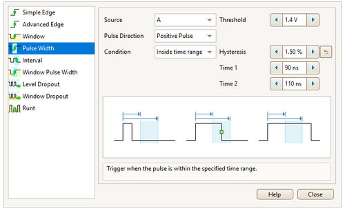
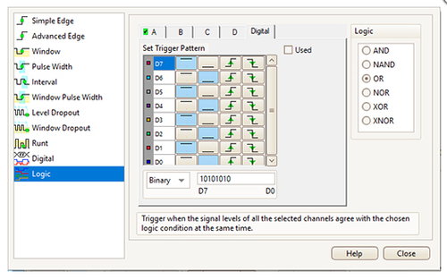
| Advanced trigger types (analog channels) | Edge, window, pulse width, window pulse width, dropout, window dropout, interval, runt, logic. | ||
| Trigger types (analog channels, ETS) | Rising or falling edge ETS trigger available on ChA only, 8-bit mode only. | ||
| Trigger sensitivity (analog channels) | Digital triggering provides 1 LSB accuracy up to full bandwidth of scope. | ||
| Trigger sensitivity (analog channels, ETS) | At full bandwidth: typical 10 mV peak to peak | ||
| Trigger types (digital inputs) | MSO models only: Edge, pulse width, dropout, interval, logic, pattern, mixed signal. | ||
| Maximum pre-trigger capture | Up to 100% of capture size. | ||
| Maximum post-trigger delay | Zero to 4 billion samples, settable in 1 sample steps (delay range on fastest timebase of 0 – 4 s in 1 ns steps) | ||
| Trigger re-arm time | 8-bit mode, typical: 1 μs on fastest timebase 8 to 12 bit modes: < 2 μs max on fastest timebase 14 to 16 bit modes: < 3 μs max on fastest timebase |
||
| Maximum trigger rate | 10 000 waveforms in a 10 ms burst, 8-bit mode | ||
| External trigger input – not MSO models: | |||
| Connector type | Front panel BNC | ||
| Trigger types | Edge, pulse width, dropout, interval, logic | ||
| Input characteristics | 1 MΩ ± 1% || 14 pF ±1.5 pF | ||
| Bandwidth | 60 MHz | 100 MHz | 200 MHz |
| Threshold range | ±5 V | ||
| Threshold range | ±5 V, DC coupled | ||
| External trigger threshold accuracy | ±1% of full scale | ||
| External trigger sensitivity | 200 mV peak to peak | ||
| Coupling | DC | ||
| Overvoltage protection | ±100 V (DC AC peak) | ||
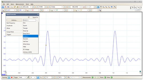
| Function generator: | |
|---|---|
| Standard output signals | Sine, square, triangle, DC voltage, ramp up, ramp down, sinc, Gaussian, half-sine |
| Pseudorandom output signals | White noise, selectable amplitude and offset within output voltage range. Pseudorandom binary sequence (PRBS), selectable high and low levels within output voltage range, selectable bit rate up to 20 Mb/s |
| Standard signal frequency | 0.025 Hz to 20 MHz |
| Sweep modes | Up, down, dual with selectable start / stop frequencies and increments |
| Triggering | Can trigger a counted number of waveform cycles or frequency sweeps (from 1 to 1 billion) from the scope trigger, external trigger or from software. Can also use the external trigger to gate the signal generator output. |
| Output frequency accuracy | Oscilloscope timebase accuracy ± output frequency resolution |
| Output frequency resolution | < 0.025 Hz |
| Output voltage range | ±2 V |
| Output voltage adjustments | Signal amplitude and offset adjustable in approx 0.25 mV steps within overall ±2 V range |
| Amplitude flatness | < 1.5 dB to 20 MHz, typical |
| DC accuracy | ±1% of full scale |
| SFDR | > 70 dB, 10 kHz full scale sine wave |
| Output characteristics | 50 Ω ±1% |
| Connector type | BNC(f) |
| Overvoltage protection | ±20 V |
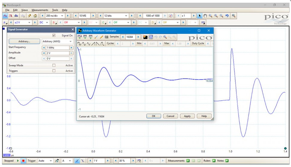
| Arbitrary Waveform Generator: | |
|---|---|
| Update rate | 200 MHz |
| Buffer size | 32 kS |
| Resolution | 14 bits (output step size approximately 0.25 mV) |
| Bandwidth | >20 MHz |
| Rise time (10% to 90%) | < 10 ns (50 Ω load) |
| Additional AWG specifications including sweep modes, triggering, frequency accuracy and resolution, voltage range, DC accuracy and output characteristics are as the function generator | |
| Probe compensation pin | |
| Output characteristics | 600 Ω |
| Output frequency | 1 kHz |
| Output level | 3 V peak to peak, typical |
| Overvoltage protection | 10 V |
| Spectrum analyser: | ||||||
|---|---|---|---|---|---|---|
| Frequency range | DC to 60 MHz | DC to 100 MHz | DC to 200 MHz | |||
| Display modes | Magnitude, average, peak hold | |||||
| Y axis | Logarithmic (dbV, dBu, dBm, arbitrary dB) or linear (volts) | |||||
| X axis | Linear or logarithmic | |||||
| Windowing functions | Rectangular, Gaussian, triangular, Blackman, Blackman–Harris, Hamming, Hann, flat-top | |||||
| Number of FFT points | Selectable from 128 to 1 million in powers of 2 | |||||
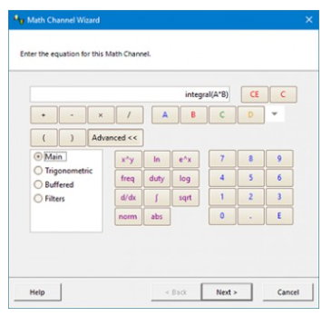
| Math channels: | ||||||
|---|---|---|---|---|---|---|
| Functions | −x, x y, x−y, x*y, x/y, x^y, sqrt, exp, ln, log, abs, norm, sign, sin, cos, tan, arcsin, arccos, arctan, sinh, cosh, tanh, delay, average, frequency, derivative, integral, min, max, peak, duty, highpass, lowpass, bandpass, bandstop | |||||
| Operands | A, B, C, D (input channels), T (time), reference waveforms, pi, D0−D15 (digital channels), constants | |||||
| Automatic measurements: | |
|---|---|
| Scope mode | AC RMS, true RMS, frequency, cycle time, duty cycle, DC average, falling rate, rising rate, low pulse width, high pulse width, fall time, rise time, minimum, maximum, peak to peak |
| Spectrum mode | Frequency at peak, amplitude at peak, average amplitude at peak, total power, THD %, THD dB, THD N, SFDR, SINAD, SNR, IMD |
| Statistics | Minimum, maximum, average and standard deviation |
| DeepMeasure™ | |
| Parameters | Cycle number, cycle time, frequency, low pulse width, high pulse width, duty cycle (high), duty cycle (low), rise time, fall time, undershoot, overshoot, max. voltage, min. voltage, voltage peak to peak, start time, end time |
| Serial decoding: | |
|---|---|
| Protocols | 1-Wire, ARINC 429, CAN & CAN-FD, DCC, DMX512, Ethernet 10Base-T and 100Base-TX, FlexRay, I²C, I²S, LIN, PS/2, MODBUS, SENT, SPI, UART (RS-232 / RS-422 / RS-485), USB 1.1 |
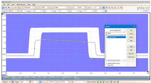
| Mask limit testing: | |
|---|---|
| Statistics | Pass/fail, failure count, total count |
| Mask creation | User-drawn, table entry, auto-generated from waveform or imported from file |
| Display: | |
| Interpolation | Linear or sin(x)/x |
| Persistence modes | Digital color, analog intensity, custom, fast |
| Software: | |
|---|---|
| Windows | PicoScope for Windows For Windows 7, 8 and 10 |
| Languages | Chinese (simplified), Chinese (traditional), Czech, Danish, Dutch, English, Finnish, French, German, Greek, Hungarian, Italian, Japanese, Korean, Norwegian, Polish, Portuguese, Romanian, Russian, Spanish, Swedish, Turkish |
| General: | ||||||
|---|---|---|---|---|---|---|
| PC connectivity | USB 3.0 SuperSpeed (USB 2.0 compatible) | |||||
| Power requirements | 2-channel models: powered from single USB 3.0 port 4-channel models: AC adaptor supplied. Can use 2 channels (plus MSO channels if fitted) powered by USB 3.0 or charging port supplying 1.2 A. |
|||||
| Dimensions | 190 x 170 x 40 mm including connectors | |||||
| Weight | < 0.5 kg | |||||
| Temperature range | Operating: 0 to 40 °C 15 to 30 °C for quoted accuracy after 1 hour warm-up Storage: –20 to 60 °C |
|||||
| Humidity range | Operating: 5 to 80 %RH non-condensing Storage: 5 to 95 %RH non-condensing |
|||||
| Environment | Up to 2000 m altitude and EN61010 pollution degree 2 | |||||
| Safety approvals | Designed to EN 61010-1:2010 | |||||
| EMC approvals | Tested to EN61326-1:2013 and FCC Part 15 Subpart B | |||||
| Environmental approvals | RoHS and WEEE compliant | |||||
| PC requirements | Processor, memory and disk space: as required by the operating system Port(s): USB 3.0 or USB 2.0 |
|||||
| Total Satisfaction Guarantee | In the event that this product does not fully meet your requirements you can return it for an exchange or refund. To claim, the product must be returned in good condition within 14 days. | |||||
| Warranty | 5 years | |||||
Order your 5000D PicoScope Online:
| Model | |||
|---|---|---|---|
| 2 Channel | BANDWIDTH (MHz) | Product # | Price: |
| 5242D | 60 | PQ143 | |
| 5243D | 100 | PQ144 | |
| 5244D | 200 | PQ145 | |
| 5242D MSO | 60 | PQ149 | |
| 5243D MSO | 100 | PQ150 | |
| 5244D MSO | 200 | PQ151 | |
| 4 Channel | BANDWIDTH (MHz) | Price: | |
| 5442D | 60 | PQ146 | |
| 5443D | 100 | PQ147 | |
| 5444D | 200 | PQ148 | |
| 5442D MSO | 60 | PQ152 | |
| 5443D MSO | 100 | PQ153 | |
| 5444D MSO | 200 | PQ154 | |
-->Need 4 Channels while using your Laptop and no power? Get the cable indicated at this link: USBA2M
Accessories:
Passive oscilloscope probe: 100 MHz bandwidth 1:1/10:1 switchable, BNC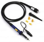
TA375
Order:
Passive oscilloscope probe: 200 MHz bandwidth 1:1/10:1 switchable, BNC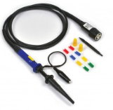
TA386
Order: