| Tech Tip: Zero Offset function in PicoScope 6
Q. Ever wished you could null out the voltage offset on your scope or an attached probe?
A. PicoScope 6 now includes this function as part of its Channel Options menu. Click the channel name (such as A) on the toolbar to see this menu, which has a Zero Offset section. After you click Zero you will be asked to remove any probe from the input channel and short-circuit the input to eliminate stray voltages. PicoScope will then perform the adjustment automatically.

Zero Offset is available on all PicoScope oscilloscopes and is handled digitally. A related feature called DC Offset, which operates on the analog signal, is available on PicoScopes with the necessary hardware. It allows you to apply an arbitrary offset voltage to avoid saturating the input. See your PicoScope 6 User's Guide for a list of devices that include this feature.
X10 Scaling
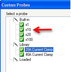
Q. I'm new to this product [the PicoScope 3204B]. I like it. Is there a way to make the oscilloscope scale the vertical axis by x10? I'm using the x10 setting on the probe, and, yes, I can multiply by 10 in my head. But I prefer to set up the software to do that calculation for me, if possible.
A. PicoScope can easily do this. Click the Channel Settings button (marked with the channel letter and a black arrow) and change the Probe setting to x10. Other probe types are also listed.
Sending an output signal conditional on input
Q. I want to use my PicoScope 2205 MSO as a relay in a closed-loop system. I want to send an output signal when the input is below a certain value. Any thoughts on how I can achieve this?
A. PicoScope 6.7 has a triggered signal generator feature that allows you to set up a trigger on a scope input and use that to trigger the output of the signal generator. The Latest Features in PicoScope 6 video (time 3:53) shows you how to do it. You can set up a repeat trigger by using the required voltage level and specifying a falling edge.
Serial decoding with the PicoScope 4226 and 4227
Speed and Precision: In last month's newsletter we introduced the new PicoScope 4226 and 4227, our 6th generation of high-resolution oscilloscopes. These 12-bit scopes have bandwidths of 50 and 100 MHz and sampling rates of 125 and 250 MS/s. One of the other features that may have sparked your interest is serial data decoding, so we're going to look at that in more detail this month.
CAN and I2C: Two serial formats are currently supported: CAN Bus and I2C. We know that many users would like additional formats, so we are working to extend this list. Serial decoding is integrated into the main PicoScope display, so there is no need to learn a new layout and controls. When you select Serial Decoding from the Tools menu, PicoScope asks you to select which channel to decode. CAN decoding requires a single channel, while I2C requires two channels for data and clock. You can either specify the data rate or let PicoScope auto-detect it.
Waveform and Table displays: The 32-megasample buffer of the PicoScope 4226 and 4227 is large enough to capture thousands of data packets or frames with accurate timing. The decoded data is then displayed underneath the waveform, so you can monitor the signal quality at the same time as the data. Errors are shown as red data values. For maximum information, you can view the data in a table that describes every frame or packet in detail. If too much information is displayed, you can filter the data to show only the packets of interest. You can also tell PicoScope wait for a specified data value in a specified field before beginning decoding.
Other Scopes: If you don't have a PicoScope 4226 or 4227, don't worry: PicoScope's serial decoding feature works on all our USB scopes. You just need to make sure that the scope has enough memory to capture the data packets of interest with enough time resolution. PicoScope will tell you if there are not enough samples to decode the data.
Read about the PicoScope 4226 and 4227, download a brochure or place an order - US Prices or CDN Prices
PicoScope features presented in the past that may have been missed:
We are continually adding features to PicoScope 6 to make it easier to use. Here are a few measurement-related features that you may have missed:
- Editable rulers: Rulers are the dashed lines that you can drag onto a waveform to measure voltage or time. When rulers are in use, a table appears showing all of the ruler measurements. Did you know that you can edit these measurements by clicking on them and typing a new value, and the rulers will move accordingly? This makes it easy to set accurate limits for pass/fail tests.
- Ruler legend: The ruler legend (the table showing the ruler measurements) has 'minimize' and 'close' buttons in the top right corner. Minimizing the table shrinks it to save space without disturbing the rulers. Closing the table instantly removes all the rulers.
- Tracking rulers: In the ruler legend, you will see a padlock symbol at the end of each row. This is normally unlocked, meaning that the two rulers on that channel are independent. Clicking the symbol changes the rulers to 'locked' mode, which forces the rulers to follow each other when dragged. This is useful when you want to display a fixed time or voltage interval.
If your version of PicoScope 6 doesn't have these features, download a free update now.
Q. I notice that you can use PicoScope's Math function for Averaging and that the default number of waveforms held by the buffer is 32. What is the maximum number of waveforms I can average? Or is there a formula I can use to calculate this?
A. When PicoScope is stopped, adding a new Average() math channel gives you the average of all the waveforms in the buffer. Although the default number of waveforms in the buffer is 32, you can change it to any number from 1 to 10,000. The setting is in Tools > Preferences > General > Waveform Buffer. This is a maximum, not a guaranteed value, as the actual number of waveforms depends on the capture size and available storage space. When PicoScope is running, the Average() channel gives you a continuous average of all waveforms since the start of capture and so is not limited to the buffer size.
Tech Tips: PicoScope 6
Mouse wheel
Did you know that your mouse wheel can save you time in PicoScope 6? As well as the keyboard shortcuts for adjusting timebase and other controls, the mouse wheel operates on whichever scrollable control is in focus. For example, click twice on the arrow next to the timebase control so that the timebase setting is in focus (a dotted rectangle will appear around it). You can now change timebase by turning the mouse wheel.

Movable trigger toolbar

Did you also know that the triggering toolbar (initially at the bottom of the PicoScope 6 window) can be switched to the top of the window? This is useful when your Windows (or other) taskbar keeps popping up over the top of your PicoScope window, hiding the trigger controls. To move the triggering toolbar, go to Tools > Preferences > Options and check Move Trigger toolbar to top.
PicoScope 6 - Advanced Trigger video
Tech Tips: FFT amplitude, UART decoding
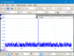
Q. I would like to know why the FFT of a 1 kHz sine wave of 2 V amplitude gives a peak at 1 kHz of only 1.3 V in PicoScope. The spectrum mode was set to linear amplitude and a Blackman window.
A. The amplitude in FFT is the root mean square (RMS) value of the waveform. The FFT settings, such as the number of bins, where the bins fall in relation to the signal frequency and the window function used, will also affect the results. A flat-top window is best for accurate measurement of amplitude. For a 2 V peak (4 V peak to peak) sine wave the RMS value is 1.414 V. This is close to your measured value of 1.3 V. The remaining error might be due to distortion in the signal, if some of the energy has been diverted from the fundamental into the harmonics.
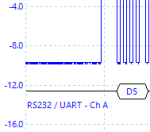
Q. I wonder if PicoScope 6 can decode RS-485 as it decodes RS-232....
A. Yes, it can. RS-232 and RS-485 both use the same UART communication and can be decoded in PicoScope 6. We recently renamed the decoder to "UART (RS-232, RS-422, RS-485)" to make this clearer. In fact you can decode any UART signal regardless of the electrical standard, including TTL and CMOS.
|
  |
| |
|