


I would like to post and share this test procedure using the WPS pressure transducer.
Possibly one of the most valuable and conclusive test procedures we have when diagnosing common rail diesel systems is the “Spill Test” or “Back leakage test”
Spill or back leakage is an essential feature of the common rail diesel systems confirming adequate lubrication of the injector assemblies, whilst providing a degree of cooling as a beneficial side effect.
Traditionally we have measured the volume of “back leakage” using graduated collection bottles, whilst monitoring both the rate and amount of “fill” during cranking or pre-set running conditions.
The back leakage test will always remain relevant as manufactures often specify the volume of back leakage against time (Cubic Centimetres per seconds CC/S)
There is however an alternative using the WPS500X pressure transducer that offers some additional advantages.
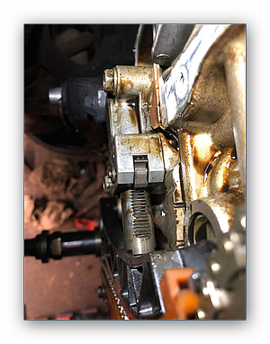
1. Connecting the WPS in series with the injector spill return hose will enable the technician to measure the back leakage pressure/pulsations under numerous engine speed and load conditions. The technician can now monitor the contributing back leakage pressure from each injector whilst road-testing the vehicle under the conditions described by the customer or DTC “freeze frame data”.
2. The WPS500X pressure transducer will need only one connection into the back leakage return pipework as opposed to disrupting 4 x injector spill hoses on a four cylinder engine.
3. Using the WPS transducer in conjunction with PicoScope will provide a hard copy of test results including any relevant engine test conditions such as RPM, MAF, MAP Fuel Pressure etc. This builds customer confidence and provides feedback to warranty/insurance companies.
After connection, start the engine and allow the back leakage to bleed through the spill test pipes, WPS pressure transducer, then on into the sealed container.
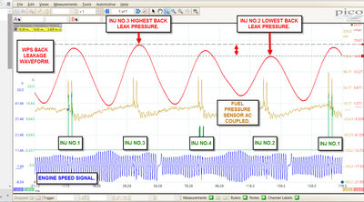
With the WPS transducer and spill hoses bled, you will now be able to monitor the back leakage pressure and using the signal from number 1 injector, identify the pulsations using the firing order.
When using the scope we are always looking for uniformity/anomalies and should all injectors be performing equally, (balanced) we should see even pulsations within the back leakage waveform
Should you identify any irregularity, by using the additional number 1 injector signal and the firing order sequence you will be able to identify the offending injector and act accordingly?
Note: Using the WPS transducer will enable back leakage evaluation under road test conditions so capturing those illusive, intermittent running issues.
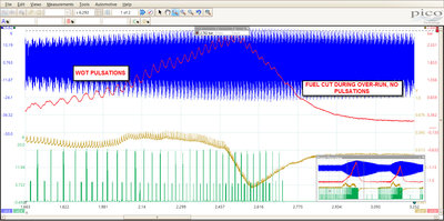
Below is an overview of the back leakage pressure under idle to WOT conditions. The crankshaft signal (Blue) indicates the engine speed, the back leakage pressure is indicated using channel B (Red) revealing the various stages of back leakage pressure. Using the zoom feature of PicoScope you are able to zoom into any area of this capture and monitor the back leakage pressure under various engine running conditions. Notice on over-run how the back leakage pulsations clear during the “fuel cut stage” (No injection=no pulsation)
of_wot_spill_test.jpg)
Below is a zoomed image of the WOT to the over-run stage
 BACK LEAKAGE TEST.psdata
- (2.74 MiB)