The primary ignition is so called as it forms the first part of the ignition circuit. The primary circuit is used to provide the initial stage towards the secondarys High Tension (HT) output.
The primary circuit has evolved from the basic contact breaker points and condenser, to the distributorless and coil per cylinder systems in common use today. The basic origin of all of these systems evolves around the magnetic inductance principal. The only system to differ from this principal is capacitive discharge, whose operation will be detailed in a later topic.
This principle is based around a magnetic field (or flux) being produced when the coil's earth circuit is completed by either the contacts or the amplifier providing the coil negative terminal with a path to earth. When this circuit is complete, a magnetic field is produced and builds until the coil's magnetic field becomes maximised or saturated. At the predetermined point of ignition, the coil's earth is removed and the magnetic field or flux collapses across the coils 250 to 350 primary windings, which in turn induces a voltage of 200 to 350 Volts.
This induced voltage will be determined by the following factors:
- The number of turns in the coils primary winding
- The strength of the magnetic field
- The rate of collapse, which is determined by the speed of the switching of the earth path
The number of turns within the coils primary is preset from manufacture, however the strength of the magnetic field which is proportionate to the current within the circuit and the speed of the switching, can be seen in Fig 1.0
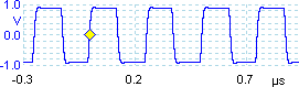
Figure 1.0
The current within the electronic ignition example shown sharply rises to 6 Amps, at which point the current is held until the earth circuit is removed. The switching speed can be seen by the angle of the vertical line at the end of the trace, any delay or slow switching will be seen as a sloping line. Any compromise in the switching speed will result in a lower induced voltage.
The height of the induced voltage line can be seen in Fig 1.1, in this particular instance its maximum voltage is 326 Volts. This is a result of the magnetic flux passing quickly across the coils primary windings. It is important to test this voltage as a low secondary HT output could result from a low primary voltage.
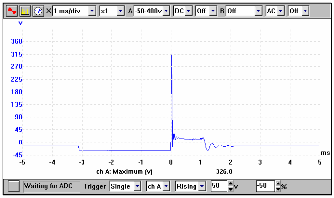
Figure 1.1
Dwell Period
Dwell is measured as an angle: with contact ignition, the points gap determines the dwell angle. The definition of contact ignition dwell is: ‘the number of degrees of distributor rotation with the contacts in the closed position’. As an example, a 4 cylinder engine will have a dwell of approximately 45 degrees, which is 50% of one cylinders complete primary cycle.
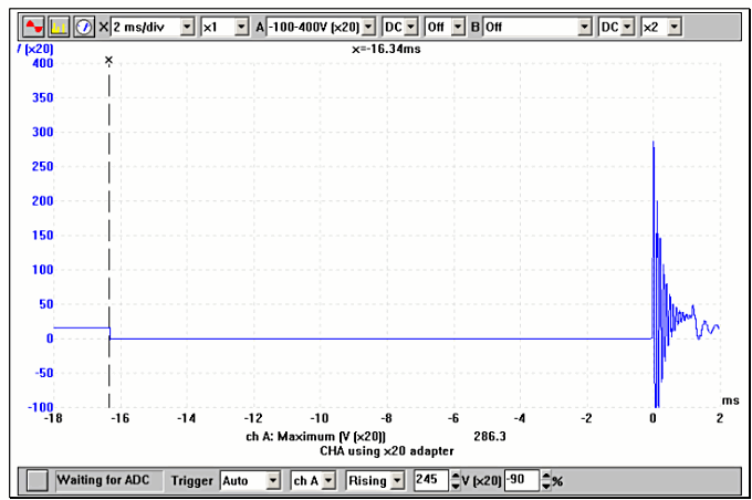
Figure 1.2
One of the many compromises with contact ignition is the fact that the coils saturation time will reduce with increasing engine speed. In the illustration shown in Fig 1.2, the engine is running at approximately 1000 rpm and the points are closed for 16.3 milliseconds. This results in an induced voltage of 286.3 Volts. As the engine speed is increased to 3000 rpm the coils available time to fully ‘saturate’ will be reduced pro-rata. Illustration Fig 1.3 shows that the time available to charge the coil has now been reduced to 5.6 milliseconds. As a result, the induced voltage has been reduced to 275.4 Volts and the coils HT output reduced accordingly.
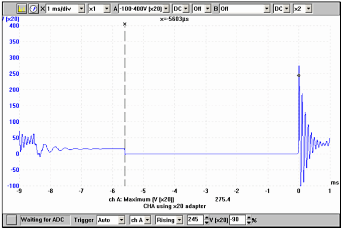
Figure 1.3
The dwell period on an engine with electronic ignition is controlled by the current limiting circuit within the amplifier or Electronic Control Module (ECM). The dwell on a variable dwell or constant energy system will be seen to expand as the engine speed increases, compensating for the shorter time period.
The term ‘constant energyfacturer"> OEM PATS immobiliser was having any influence. They were sure of a spark present at all plugs and the injectors were indeed firing. This, coupled with the fact that the PATS MIL wasn’t flagging a fault, didn’t at this stage give any cause for concern, so I moved on to other more likely areas. A point which everybody was sure about was that the car ran perfectly before the customer got his hands on it.
I felt that the garage was right on track with an ignition timing issue, but just hadn’t managed to pinpoint the fault yet. If there’s one thing I preach it’s always start at the beginning. If we are dealing with a timing issue, we need to look at when ignition is occurring and compare it to crank rotation and piston position.
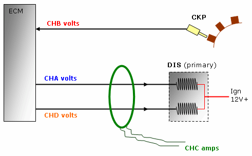
This engine uses a simple ignition system. The basis of its operation is that the ECM collects information from the CKP sensor and emits two separate primary dwell commands to a single DIS pack.
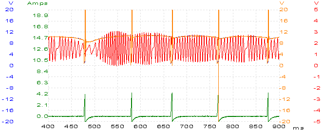
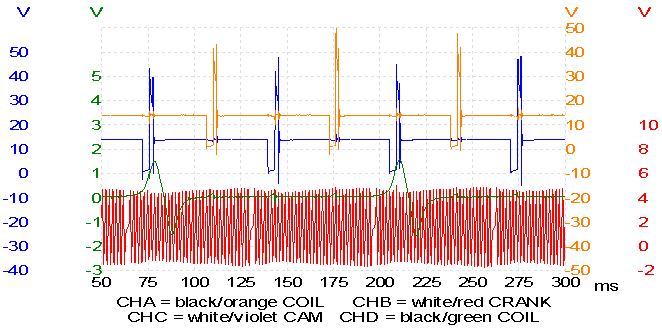
Figure 2
Figure 2 shows a typical capture with the engine cranking and our fault present. All trace captures were taken with the scope’s common (black lead) connected to the vehicle’s chassis ground. When capturing a trace, many people attach great importance to where to stick the red probe without giving proper consideration what to do with the black probe; yet the quality of the result relies equally on both probes.
Channel A (red) — We see a good crank rotation and speed with no obvious signal anomalies. This CKP circuit uses a variable-reluctance sensor with both attached cables carrying the AC generated signal. The circuit is biased at about 1.5 V to aid the ECM’s self-check. There are a few traps to beware of: most important is to make sure you are monitoring the correct cable, so that you keep the test results constant and reliable and always with the same trace polarity. Here both CKP cables will give very similar trace patterns, but one will be the inverse of the other and it’s difficult to tell which is right and which is wrong for a particular system. I probed the White/Red cable, compared it to a previously stored known good capture, and it checked out OK.
We also can get a good visual correlation as the engine attempts to lock from our suspected timing error.
Channel B (blue)— The trace is difficult to see but it is there, hiding behind the Channel D (orange) trace, which is odd. I would expect to see the dwell commands alternate between 1 and 4, then 2 and 3, and back to 1 and 4 with all commands being 180° apart with respect to crank position. According to the capture, the cylinder 1 and 4 dwell period is occurring at precisely same time as the cylinder 2 and 3 dwell period. It also seems that the reverse is true; 2-and-3 is occurring at the same time as 1-and-4. There’s something not right, and it confirms an ignition timing issue.

Figure 3
Figure 3 shows one of the primary ignition pulses from the previous capture in more detail. This is where the powerful zoom built in to the PicoScope software comes in handy.
Channel C (green) — At the time of hook-up I don’t know what I’m going to find, so it makes sense to get as big a picture as possible about what is going on, as sometimes only one channel trace may prove to be of any value. What clearly needs investigating further is the presence of both coil primary commands at the same time, causing plugs 1, 2, 3, 4 all to fire together. Does the ECM know it’s doing this? Some weird default strategy? Maybe the garage was right: a broken ECM.
I’ve touched on this subject before in other case studies: when a diagnosis is taking me down the road of a new control unit I get suspicious that there’s still something waiting to be found. The next step is to test the relevant cabling and attached components. As the circuit illustration earlier shows, this system is simple enough for us to work out a checking procedure. The ECM power supplies were checked and confirmed even though this really didn’t seem a likely cause of the fault — it was nevertheless still an important step. It wasn’t long, after collecting a few meter readings, that one particular resistance value didn’t seem right.
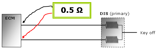
With key off, I checked the circuit resistance between one DIS primary cable and the other. Ordinarily I would err on the side of caution when taking resistance readings with a control unit still connected, because semiconductor susceptibility and meter polarity issues can give false meter readings and send you off on a two-hour ghost hunt. However, with this problem, it was important that I saw what the ECM was seeing. I expected a low reading somewhere in the region of 2 ohms, but my reading was too low.
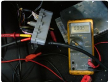
Then, with the ECM isolated, I got the same 0.5 ohm reading, so this obviously eliminated the ECM as a possible cause. What nailed this fault was when I disconnected the DIS pack from the other end and got the same 0.5 ohm. The coil command lines were shorted together!
This now made perfect sense and tied cause and effect together nicely.
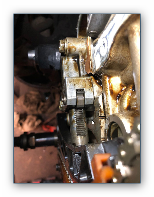
Figure 6 shows a hole that was discovered. This was drilled into the bulkead — a popular place for routing extra power cables for in-car entertainment. Twisting round the engine harness revealed severe cable damage.
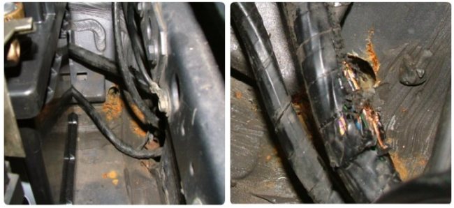
Figure 6.
Remember the customer’s additional inventory put on the car...
Stripping back the insulation I found that a lot of cable strands had suffered, which meant that new cabling had to be soldered in. With the repair in place, the engine fired up for the first time in weeks. From here on I recommended an oil and filter change to remove heavy fuel deposits from the weeks of cranking, and a decent run at cruise speed to clear out the exhaust stream and regain suitable closed loop and emissions. Figure 7 shows the patterns I was expecting to see earlier.