|
|
||||
| Log In | ||||
|
| ||||
| ||||
| ||||
| ||||
| ||||


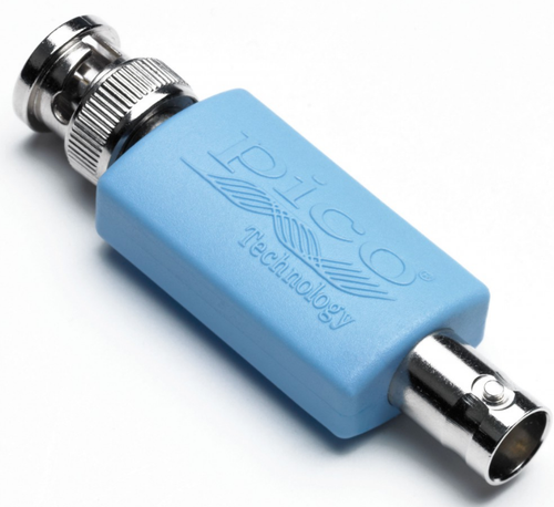
With high bandwidth and fault-protection, the 10:1 attenuator has been designed to allow fuel injector and primary ignition waveforms to be measured using PicoScope oscilloscopes. The TA197 is a passive 10:1 attenuator. This means that a 10 V signal at its input will appear as a 1 V signal on the output. The TA197 allows voltages of up to 400 V to be measured. The TA197 attenuator also increases the input impedance of the oscilloscope from 1 MΩ to 8 MΩ and can also be used when measuring the output of high-impedance sensors such as piezo knock sensors where connecting an automotive scope can attenuate the signal or induce a fault code. Note : When using a PicoScope 4225 or 4425 oscilloscope the attenuator is not normally needed for measuring injectors as the voltage spike is usually under 200 V. It will be required however when using older generations of PicoScopes which only measure to 50 V or 100 V. The 10:1 attenuator is an improved version of the 20:1 attenuator previously available from Pico. Safety PrecautionsThe TA197 is designed for measuring automotive signals such as fuel injector and primary ignition voltages (nominally 6, 12 or 24 volts). This attenuator must not be used to measure mains voltages, secondary ignition or other hazardous voltages. Fuel injector and primary ignition signals contain short duration high voltage spikes “inductive kicks”. We therefore recommend the use of two ground connections between the oscilloscope and the vehicle under test. One ground connection is made using the measurement test lead. A second ground lead should be connected between one of the BNC connectors on the oscilloscope and a secure ground point on the vehicle such as the negative terminal of the battery. Misconfiguration and/or failure to follow these warnings may cause damage to the product and/or computer and could cause injury to yourself or others.
|
||||||