


|
|
|||
| Log In | |||
|
| |||
| |||
| |||
| |||


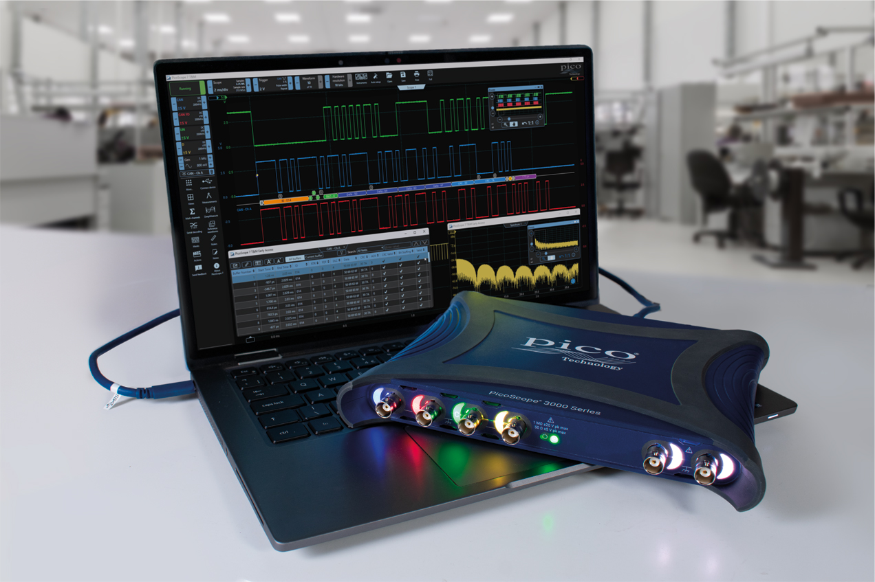
PicoScope 3417e & 3418e Series 350 or 500 MHz5 GS/s digital USB oscilloscope[PQ347 & PQ349]
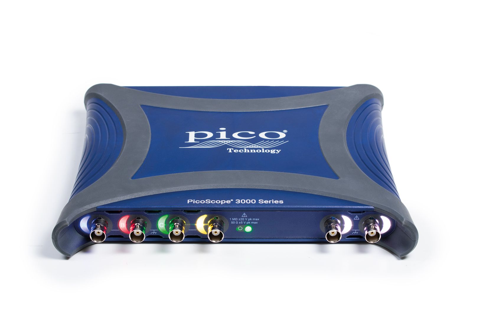
PicoScope 3417E - [PQ347] or 3418E - [PQ349] inputs, outputs and indicatorsChannel trace color indicators Rear Panel SuperSpeed USB-Connection
Features THE deep memory oscilloscopePicoScope 3000E Series oscilloscopes have waveform capture memories of up to 2 billion samples – many times larger than competing scopes. Deep memory enables the capture of long-duration waveforms at maximum sampling speed which is invaluable for capturing signals ranging from fast serial data through to complex power supply start-up sequences. The waveform shows a capture of 500 million samples with a zoom factor of 10,000 to reveal details of individual pulses.

Other functions included such as mask limit testing and color persistence mode, PicoScope software enables you to zoom into your waveform up to 100 million times. The Zoom window allows you to easily control the size and location of the zoom area. Other tools, such as the waveform buffer, serial decoding and hardware acceleration work with the deep memory, making the PicoScope 3000E Series a powerful, compact package. More information on Deep memory Waveform buffer and navigatorHave you ever seen a glitch on an oscilloscope screen but by the time you stop the scope it has gone? PicoScope can store the last 40,000 oscilloscope or spectrum waveforms in its circular waveform buffer, effectively letting you turn back time to find that elusive waveform. 
Hardware acceleration engine (HAL4)Some oscilloscopes struggle when you enable deep memory; the screen update rate slows and the controls become unresponsive. The PicoScope 3000E Series avoids this limitation with the use of a dedicated fourth-generation hardware acceleration (HAL4) engine inside the oscilloscope.
Its massively parallel design effectively creates the waveform image to be displayed on the PC screen and allows the continuous capture and display to the screen of up to 2 billion samples every second.
The hardware acceleration engine eliminates any concerns about the USB connection or PC processor performance being a bottleneck. 
THE oscilloscope for measurements and mathMeasurements: Introduction
PicoScope 7 provides dozens of automated measurements both for the oscilloscope and spectrum, not just standard ones like frequency but more complex ones such as overshoot, edge count, phase, power factor, THD and SINAD. Statistics can be displayed to show the Average, Mean, Maximum, Minimum, Standard Deviation and a count of the number of waveforms. Measurements are highly configurable allowing you to measure across the whole waveform, between rulers or just a single cycle.
Measurements: pass/failure limits
PicoScope software offers pass/failure limits for any measurement. This gives a visual indication within the measurement window whenever the measurement result goes above or below a specified value. Pass/failure limits can be combined with actions to immediately alert the user or execute other actions when a measurement threshold has been exceeded, either above or below set limits. By filtering the waveform buffer to show only those waveforms failing a measurement limit, you can quickly identify points of interest out of the thousands of waveforms captured in the deep memory of your PicoScope. 
Measurements: logging (trending)
PicoScope allows the results of measurements to be recorded in a file for later analysis. The resulting log can be used to characterize the performance of a circuit over medium or long-duration tests – such as when evaluating drift due to thermal and other effects, or can be used to check functionality against an externally controlled variable such as supply voltage. 
DeepMeasureTM - One waveform, millions of measurements
The measurement of waveform pulses and cycles is key to verifying the performance of electrical and electronic devices.
DeepMeasure delivers automatic measurements of important waveform parameters, such as pulse width, rise time and voltage, for every individual cycle in the captured waveforms. Up to a million cycles can be displayed with each triggered acquisition or combined across multiple acquisitions. Results can be easily sorted, analyzed and correlated with the waveform display, or exported as a .CSV file or spreadsheet for further analysis.
For example, use DeepMeasure with PicoScope’s rapid trigger mode to capture 40 000 pulses and quickly find those with the largest or smallest amplitude, or use your scope’s deep memory to record a million cycles of one waveform and export the rise time of every single edge for statistical analysis. 
Math channel and filters
Math channels add additional traces to your waveform. You can select simple functions such as addition and inversion with a click, or you can use the equation editor to take things to the next level and create functions involving math, trigonometry, exponentials, logarithms, statistics, integrals and derivatives. 
Power measurements and mathPicoScope software offers a suite of power measurements (with more in development) and associated power math channels which include:
 Software
Specifications PicoScope 3000E Series Specifications
|
|||||||||||||||||||||||||||||||||||||||||||||||||||||||||||||||||||||||||||||||||||||||||||||||||||||||||||||||||||||||||||||||||||||||||||||||||||||||||||||||||||||||||||||||||||||||||||||||||||||||||||||||||||||||||||||||||||||||||||||||||||||||||||||||||||||||||||||||||||||||||||||||||||||||||||||||||||||||||||||||||||||||||||||||||||||||||||||||||||||||||||||||||||||||||||||||||||||||||||||||||||||||||||||||||||||||||||||||||||||||||||||||||||||||||||||||||||||||||||||||||||||||||||||||||||||||||||||||||||||||||||||||||||||||||||||||||||||||||||||||||||||||||||||||||||||||||||||||||||||||||||||||||||||||||||||||||||||||||||||||||||||||||||||||||||||||||||||||||||||||||||||||||||||||||||||||||||||||||||||||||||||||||||||||||||||||||||||||||||||||||||||||||||||||||||||||||||||||||||||||||||||||||||||||||||||||||||||||||||||||||||||||||||


| PicoScope model | PicoScope 3417E and 3417E MSO | PicoScope 3418E and 3418E MSO |
|---|---|---|
| Vertical (analog channels) | ||
| Input channels | 4 | |
| Bandwidth (–3 dB) | 350 MHz | 500 MHz |
| Rise time (10% to 90%, −2 dB full scale) | 1.2 ns | 925 ps |
| Selectable bandwidth limit 8-bit mode | 20, 50, 100, 200, 350 MHz | 20, 50, 100, 200, 350, 500 MHz |
| Selectable bandwidth limit 10-bit mode | 20, 50, 100, 200 MHz | |
| Vertical resolution | 8 bits, 10 bits | |
| Enhanced vertical resolution (software) | Hardware resolution 4 bits | |
| Input connector | BNC(f) | |
| Input characteristics 50 Ω | 50 ? ±2 % | |
| Input characteristics 1 MΩ | 1 MΩ ±1 % ? 13 pF ±2 pF | |
| Input coupling 50 Ω | DC | |
| Input coupling 1 MΩ | AC/DC | |
| Input sensitivity 50 Ω | 1 mV/div to 1 V/div (10 vertical divisions) | |
| Input sensitivity 1 MΩ | 1 mV/div to 4 V/div (10 vertical divisions) | |
| Input ranges (full scale) 50 Ω | ±5 mV[1], ±10 mV[2], ±20 mV[3], ±50 mV, ±100 mV, ±200 mV, ±500 mV, ±1 V, ±2 V, ±5 V | |
| Input ranges (full scale) 1 MΩ | ±5 mV[1], ±10 mV[2], ±20 mV[3], ±50 mV, ±100 mV, ±200 mV, ±500 mV, ±1 V, ±2 V, ±5 V, ±10 V, ±20 V | |
| [1] ±5 mV only available up to 100 MHz [2] ±10 mV only available up to 200 MHz [3] ±20 mV only available up to 350 MHz |
||
| DC gain accuracy | ±(1% of signal 1 LSB) | |
| DC offset accuracy | ±(2% of full scale 200 µV) | |
| LSB size (quantization step size) 8-bit mode | < 0.4% of input range | |
| LSB size (quantization step size) 10-bit mode | < 0.1% of input range | |
| Analog offset range (vertical position adjustment) | ±250 mV (±5 mV to ±200 mV ranges) ±2.5 V (±500 mV to ±2 V ranges) ±5 V (±5 V range, 50 Ω input) ±20 V (±5 V to ±20 V ranges, 1 MΩ input) |
|
| Analog offset control accuracy | ±1% of offset setting, additional to DC accuracy above | |
| Overvoltage protection 1 MΩ | ±100 V (DC AC peak) up to 10 kHz | |
| Overvoltage protection 50 Ω | 5.5 V RMS max, ±20 V pk max | |
| PicoScope model | 3417E MSO | 3418E MSO |
|---|---|---|
| Vertical (digital channels) - MSO only | ||
| Input channels | 16 (2 logical ports of 8 channels each) | |
| Input connector | 2.54 mm pitch, 10 x 2 way connector | |
| Maximum input frequency | 100 MHz (200 Mbit/s) | |
| Minimum detectable pulse width | 5 ns | |
| Threshold grouping | Two independent threshold controls. Port 0: D0 to D7, Port 1: D8 to D15 | |
| Threshold selection | TTL, CMOS, ECL, PECL, user-defined | |
| Threshold range | ±5 V | |
| Threshold accuracy | < ±350 mV (inclusive of hysteresis) | |
| Threshold hysteresis | < ±250 mV | |
| Input dynamic range | ±20 V | |
| Minimum input voltage swing | 500 mV peak to peak | |
| Input impedance | 200 kΩ ± 2% || 8 pF ± 2 pF | |
| Channel-to-channel skew | 2 ns, typical | |
| Minimum input slew rate | 10 V/µs | |
| Overvoltage protection | ±50 V (DC AC peak) up to 100 kHz | |
| PicoScope model | All non-MSO and MSO 3000E models | ||||
|---|---|---|---|---|---|
| Horizontal | |||||
| Maximum sampling rate (real time) | 8-bit mode, analog channels | 8-bit mode, digital channels[4] | 10-bit mode, analog channels | 10-bit mode, digital channels[4] | |
| 1 channel[5] | 5 GS/s | 1.25 GS/s | 2.5 GS/s | 1.25 GS/s | |
| 2 channels | 2.5 GS/s | 1.25 GS/s | 1.25 GS/s | 1.25 GS/s | |
| 3 or 4 channels | 1.25 GS/s | 1.25 GS/s | 625 MS/s | 625 MS/s | |
| >4 channels | 625 MS/s | 625 MS/s | 312.5 MS/s | 312.5 MS/s | |
| Max. sampling rate, continuous USB streaming into PC memory[6] (PicoScope 7) | On USB 3.0 port | On USB 2.0 port | |||
| 1 channel | ~50 MS/s | ~10 MS/s | |||
| 2 channels | ~25 MS/s | ~5 MS/s | |||
| 3 or 4 channels | ~12 MS/s | ~2 MS/s | |||
| >4 channels | ~6 MS/s | ~1 MS/s | |||
| Max. sampling rate, continuous USB streaming into PC memory[6] (PicoSDK) | On USB 3.0 port, 8-bit resolution | On USB 3.0 port, 10-bit resolution | On USB 2.0 port, 8-bit resolution | On USB 2.0 port, 10-bit resolution | |
| 1 channel | ~300 MS/s | ~150 MS/s | ~30 MS/s | ~15 MS/s | |
| 2 channels | ~150 MS/s | ~75 MS/s | ~15 MS/s | ~8 MS/s | |
| 3 or 4 channels | ~75 MS/s | ~38 MS/s | ~8 MS/s | ~4 MS/s | |
| >4 channels | ~38 MS/s | ~18 MS/s | ~4 MS/s | ~2 MS/s | |
| Max. sampling rate, USB streaming of downsampled data[7] (PicoSDK) | 8-bit resolution | 10-bit resolution | |||
| 1 channel | 1 GS/s | 500 MS/s | |||
| 2 channels | 500 MS/s | 250 MS/s | |||
| 3 or 4 channels | 250 MS/s | 125 MS/s | |||
| >4 channels | 125 MS/s | 62.5 MS/s | |||
| [4] MSO models only [5] Channel means the total number of enabled analog channels and/or 8-bit digital ports. [6] Max. sampling rates in streaming mode are dependent on the host computer performance and workload. [7] Downsampled (min/max/average/decimated) data returned continuously to PC during streaming at up to USB data bandwidth. Raw data available to read from device buffer after streaming is completed. |
|||||
| Capture memory (per channel) | 8-bit resolution | 10-bit resolution | |||
| 1 channel | 2 GS | 1 GS | |||
| 2 channels | 1 GS | 500 MS | |||
| 3 or 4 channels | 512 MS | 256 MS | |||
| >4 channels | 256 MS | 128 MS | |||
| Maximum single capture duration at maximum sampling rate (PicoScope 7) | 200 ms | ||||
| Maximum single capture duration at maximum sampling rate (PicoSDK) | 400 ms | ||||
| Capture memory (continuous streaming) (PicoScope 7) | 250 MS | ||||
| Capture memory (continuous streaming) (PicoSDK) | Buffering using full device memory, no limit on total duration of capture | ||||
| Waveform buffer (number of segments) (PicoScope 7) | 40 000 | ||||
| Waveform buffer (number of segments) (PicoSDK) | 2 000 000 | ||||
| Timebase ranges | 1 ns/div to 5000 s/div | ||||
| Initial timebase accuracy | ±5 ppm | ||||
| Timebase drift | ±1 ppm/year | ||||
| ADC sampling | Simultaneous sampling on all active channels | ||||
| PicoScope model | 3417E and 3417E MSO | 3418E and 3418E MSO |
|---|---|---|
| Dynamic performance (typical) | ||
| Crosstalk | Better than 500:1 (from DC to bandwidth of victim channel, equal voltage ranges) | |
| Harmonic distortion (10 MHz, −2 dBfs input). 8-bit | Better than –50 dB on ±50 mV to ±20 V ranges | |
| Harmonic distortion (10 MHz, −2 dBfs input). 10 bit | Better than –60 dB on ±50 mV to ±20 V ranges | |
| SFDR (10 MHz, −2 dBfs input). 8-bit | Better than 50 dB on ±50 mV to ±20 V ranges | |
| SFDR (10 MHz, −2 dBfs input). 10-bit | Better than 60 dB on ±50 mV to ±20 V ranges | |
| RMS noise | Click to see table | |
| Linearity | ≤ 2 LSB 8-bit mode ≤ 4 LSB 10-bit mode |
|
| Bandwidth flatness | ( 0.5 dB, –3 dB) from DC to full bandwidth | |
| Low frequency flatness | < ±6% (or ±0.5 dB) from DC to 1 MHz | |
| PicoScope model | 3417E and 3417E MSO | 3418E and 3418E MSO |
|---|---|---|
| Triggering | ||
| Source | Any analog channel, AUX I/O trigger MSO models: digital D0-D15 |
|
| Trigger modes | None, auto, repeat, single, rapid (segmented memory) | |
| Advanced trigger types (analog channels) | Edge (rising, falling, rising-or-falling), window (entering, exiting, entering-or-exiting), pulse width (positive or negative or either pulse), window pulse width (time inside, outside window or either), level dropout (including high/low or either), window dropout (including inside, outside or either), interval, runt (positive or negative), transition time (rise/fall), logic Logic trigger capabilities: AND/OR/NAND/NOR/XOR/XNOR function of any trigger sources (analog channels and aux input) User-defined Boolean function of any combination of analog channels plus aux input (PicoSDK only) |
|
| Trigger sensitivity (analog channels) | Digital triggering provides 1 LSB accuracy up to full bandwidth of scope with adjustable hysteresis | |
| Advanced trigger types (digital channels) | Edge (rising, falling, rising-or-falling), pulse width (positive or negative or either pulse), level dropout (including high/low or either), interval, digital pattern (combination of any digital input states qualified by one edge), logic (mixed signal) | |
| Pre-trigger capture | Up to 100% of capture size | |
| Post-trigger delay - PicoScope 7 | Zero to > 4x10⁹ samples, settable in 1 sample steps (delay range at 5 GS/s of 0.8 s in 200 ps steps) | |
| Post-trigger delay - PicoSDK | Zero to > 1x10¹² samples, settable in 1 sample steps (delay range at 5 GS/s of > 200 s in 200 ps steps) | |
| Trigger holdoff by time | Delay re-arming the trigger after each trigger event by a user-set time up to 4 x 10⁹ sample intervals. | |
| Rapid trigger mode rearm time | < 700 ns on fastest timebase | |
| Maximum trigger rate - PicoScope 7 | 40 000 waveforms in 20 ms | |
| Maximum trigger rate - PicoSDK | Number of waveforms up to memory segment count, at a rate of 2 million waveforms per second. | |
| Waveform update rate | Up to 300 000 waveforms per second in PicoScope 7 fast persistence mode | |
| Trigger time-stamping | Each waveform is timestamped with time from previous waveform, with sample-interval resolution. | |
| PicoScope model | PicoScope 3417E and 3417E MSO | PicoScope 3418E and 3418E MSO |
|---|---|---|
| Auxiliary trigger | ||
| Trigger types (triggering scope) | Edge, pulse width, dropout, interval, logic | |
| Trigger types (triggering AWG) | Rising edge, falling edge, gate high, gate low | |
| Input bandwidth | > 10 MHz | |
| Input characteristics | 3.3 V CMOS Hi-Z input, DC coupled | |
| Input threshold | Fixed threshold, low < 1 V, high > 2.3 V suitable for 3.3 V CMOS | |
| Input hysteresis | 1.3 V max (VIH < 2.3 V, VIL > 1 V) | |
| Auxiliary output function | Trigger output | |
| Output voltage | 3.3 V CMOS (VOH > 3.2 V, VOL < 0.1 V into Hi-Z) | |
| Output impedance | Approx. 270 Ω | |
| Output rise time | Measured directly at BNC: < 15 ns | |
| Coupling | DC | |
| Overvoltage protection | ±20 V peak max | |
| Connector type | BNC(f) | |
| PicoScope model | PicoScope 3417E and 3417E MSO | PicoScope 3418E and 3418E MSO |
|---|---|---|
| Function generator | ||
| Standard output signals | Sine, square, triangle, DC voltage, ramp up, ramp down, sinc, Gaussian, half-sine | |
| Output frequency range | 100 μHz to 20 MHz | |
| Output frequency accuracy | Oscilloscope timebase accuracy ± output frequency resolution | |
| Output frequency resolution | < 1 μHz | |
| Sweep modes | Up, down, dual with selectable start/stop frequencies and increments | |
| Triggering | Free-run, or from 1 to 1 billion counted waveform cycles or frequency sweeps. Triggered from scope trigger, aux trigger or manually. | |
| Gating | Waveform output can be gated (paused) via aux trigger input or software | |
| Pseudorandom output signals | White noise, selectable amplitude and offset within output voltage range Pseudorandom binary sequence (PRBS), selectable high and low levels within output voltage range, selectable bit rate up to 20 Mb/s |
|
| Output voltage range | ±2.0 V into Hi-Z (±1.0 V into 50 ?) | |
| Output voltage adjustment | Signal amplitude and offset adjustable in approx. 0.3 mV steps within overall ± 2 V range | |
| DC accuracy | ±1 % of full scale, into Hi-Z load | |
| Amplitude flatness | < 1.5 dB to 20 MHz, typical, sine wave into 50 Ω | |
| SFDR | > 70 dB, 10 kHz full scale sine wave | |
| Output resistance | 50 ? ±1% | |
| Overvoltage protection | ±20 V peak max | |
| Connector type | Front-panel BNC | |
| PicoScope model | 3417E and 3417E MSO | 3418E and 3418E MSO |
|---|---|---|
| Arbitrary waveform generator | ||
| Update rate | 200 MS/s | |
| Buffer size | 32 kS | |
| Vertical resolution | 14 bits (output step size 0.3 mV approx.) | |
| Bandwidth (−3 dB) | > 20 MHz | |
| Rise time (10% to 90%) | < 10 ns (50 Ω load) | |
| PicoScope model | 3417E and 3417E MSO | 3418E and 3418E MSO |
|---|---|---|
| Spectrum analyzer | ||
| Frequency range | DC to 350 MHz | DC to 500 MHz |
| Display modes | Magnitude, average, peak hold | |
| Y axis | Logarithmic (dBV, dBu, dBm, arbitrary dB) or linear (volts) | |
| X axis | Linear or logarithmic | |
| Windowing functions | Rectangular, Gaussian, triangular, Blackman, Blackman−Harris, Hamming, Hann, flat-top | |
| Number of FFT points | Selectable from 128 to 1 million in powers of 2 | |
| PicoScope model | 3417E and 3417E MSO | 3418E and 3418E MSO |
|---|---|---|
| Math channels | ||
| Functions | −x, x y, x−y, x*y, x/y, x^y, sqrt, exp, ln, log, abs, norm, sign, sin, cos, tan, arcsin, arccos, arctan, sinh, cosh, tanh, delay, average, frequency, derivative, integral, min, max, peak, duty, highpass, lowpass, bandpass, bandstop, coupler, top, base, amplitude, positive overshoot, negative overshoot, phase, delay, moving, deskew, true power, apparent power, reactive power, power factor, area AC, positive area AC, negative area AC, abs area AC, area DC, positive area DC, negative area DC, abs area DC | |
| Operands | A to D (input channels), D0-D15 (digital channels), T (time), reference waveforms, pi, constants | |
| PicoScope model | 3417E and 3417E MSO | 3418E and 3418E MSO |
|---|---|---|
| Automatic measurements | ||
| Scope mode | Absolute area at AC/DC, AC RMS, amplitude, apparent power, area at AC/DC, base, crest factor, cycle time, DC average, DC power, duty cycle, edge count, fall time, falling edge count, falling rate, frequency, high pulse width, low pulse width, maximum, minimum, negative area at AC, negative area at DC, negative duty cycle, negative overshoot, peak to peak, phase, positive area at AC, positive area at DC, positive overshoot, power factor, reactive power, rise time, rising edge count, rising rate, top, true power, true RMS | |
| Spectrum mode | Frequency at peak, amplitude at peak, average amplitude at peak, total power, THD%, THD dB, THD N, SINAD, SNR, IMD | |
| Statistics | Minimum, maximum, average, standard deviation | |
| PicoScope model | 3417E and 3417E MSO | 3418E and 3418E MSO |
|---|---|---|
| DeepMeasure | ||
| Parameters | Cycle number, cycle time, frequency, low pulse width, high pulse width, duty cycle (high), duty cycle (low), rise time, fall time, undershoot, overshoot, max. voltage, min. voltage, voltage peak to peak, start time, end time | |
| PicoScope model | 3417E and 3417E MSO | 3418E and 3418E MSO |
|---|---|---|
| Serial decoding | ||
| Protocols | 10BASE-T1S, 1-Wire, ARINC 429, BroadRReach, CAN, CAN FD, CAN J1939, CAN XL, DALI, DCC, Differential Manchester, DMX512, Ethernet 10BASE-T, Extended UART, Fast Ethernet 100BASE-TX, FlexRay, I2C, I2S, I3C BASIC v1.0, LIN, Manchester, MIL-STD-1553, MODBUS ASCII, MODBUS RTU, NMEA-0183, Parallel Bus, PMBus, PS/2, PSI5 (Sensor), Quadrature, RS232/UART, SBS Data, SENT Fast, SENT Slow, SENT SPC, SMBus, SPI-MISO/MOSI, SPI-SDIO, USB (1.0/1.1), Wind Sensor | |
| PicoScope model | 3417E and 3417E MSO | 3418E and 3418E MSO |
|---|---|---|
| Mask limit testing | ||
| Statistics | Pass/fail, failure count, total count | |
| Mask creation | Auto-generated from waveform or imported from file | |
| PicoScope model | 3417E and 3417E MSO | 3418E and 3418E MSO |
|---|---|---|
| Display | ||
| Display modes | Scope, XY scope, persistence, spectrum | |
| Interpolation | Linear or sin(x)/x | |
| Persistence modes | Time, frequency, fast | |
| Output file formats | csv, mat, pdf, png, psdata, pssettings, txt | |
| Output functions | Copy to clipboard, print | |
| PicoScope model | 3417E and 3417E MSO | 3418E and 3418E MSO |
|---|---|---|
| Data transfer | ||
| Captured waveform data USB transfer rate to PC | On USB 3.0, PC dependent: 8-bit mode: up to 360 MS/s; 10-bit mode: up to 180 MS/s On USB 2.0, PC dependent: 8-bit mode: up to 40 MS/s; 10-bit mode: up to 20 MS/s |
|
| Hardware accelerated waveform display rate | Hardware acceleration enables over 2 GS of data to be displayed on screen per second (8-bit mode, 4 channels, 250 MS per channel at max sample rate) | |
| PicoScope model | 3417E and 3417E MSO | 3418E and 3418E MSO |
|---|---|---|
| General specifications | ||
| PC connectivity | USB 3.0 SuperSpeed (USB 2.0 compatible) | |
| PC connector type | USB 3.0 Type C | |
| Power requirement | Powered from single USB Type-C 3 A port or from USB port plus external Type-C PSU (5V, 3A) | |
| USB cables included | Type C-A 0.9 m and Type C 1.8 m | |
| Status indicators | RGB LED per BNC connector plus power and status | |
| Thermal management | Automatic fan speed control for low noise | |
| Dimensions | 221 x 173 x 30 mm | |
| Weight | < 0.7 kg | |
| Ambient temperature range - Operating | 0 to 40 °C | |
| Ambient temperature range - For quoted accuracy | 15 to 30 °C after 20-minute warm-up | |
| Ambient temperature range - Storage | –20 to 60 °C | |
| Humidity range - Operating | 5 to 80 %RH non-condensing | |
| Humidity range - Storage | 5 to 95 %RH non-condensing | |
| Altitude | Up to 2000 m | |
| Pollution degree | EN 61010 pollution degree 2: “only nonconductive pollution occurs except that occasionally a temporary conductivity caused by condensation is expected” | |
| Safety compliance | Designed to EN 61010-1 | |
| EMC compliance | Tested to EN 61326-1 and FCC Part 15 Subpart B | |
| Environmental compliance | RoHS, REACH & WEEE | |
| Warranty | 5 years | |
| PicoScope model | 3417E and 3417E MSO | 3418E and 3418E MSO |
|---|---|---|
| Software | ||
| Windows software (64-bit)[8] | PicoScope 7, PicoLog 6, PicoSDK (Users writing their own apps can find example programs for all platforms on the Pico Technology organization page on GitHub). | |
| macOS software (64-bit)[8] | PicoScope 7, PicoLog 6 and PicoSDK | |
| Linux software (64-bit)[8] | PicoScope 7 software and drivers, PicoLog 6 (including drivers) See Linux Software and Drivers to install drivers only | |
| Raspberry Pi 4B & 5 (32-bit Raspberry Pi OS)[8] | PicoLog 6 (including drivers) See Linux Software and Drivers to install drivers only | |
| [8] See the picotech.com/downloads page for more information. | ||
| Languages supported - PicoScope 7 | English-US, English-UK, Bulgarian, Czech, Danish, German, Greek, Spanish, French, Korean, Croatian, Italian, Hungarian, Netherlands Dutch, Japanese, Norwegian, Polish, Portuguese-Brazilian, Portuguese, Romanian, Russian, Slovene, Serbian, Finnish, Swedish, Turkish, Simplified Chinese, Traditional Chinese | |
| Languages supported - PicoLog 6 | Simplified Chinese, Dutch, English (UK), English (US), French, German, Italian, Japanese, Korean, Russian, Spanish | |
| PC requirements | Processor, memory and disk space: as required by the operating system Ports: USB 3.0 (recommended) or 2.0 (compatible) | |
xxxx
Documents
Documents for PicoScope 3000E Series |
||||
| Title | Language | Issue | Size | Updated |
| PicoScope 3000E Series Data Sheet | English | 1 | 8 Mb | June 2024 - Download |
| PicoScope 3000E Series User’s Guide | English | 1 | 5 | June 2024 - Download |
Order your 3417E [PQ347] - 350 MHz Scope Kit Here:
Order your 3418E [PQ349] - 500 MHz Scope Kit Here:
| 3000E Accessory Pricing | |
| P1053 500 MHz 10:1 passive BNC probe [Dual Pack] - TA562 |
P1053 500 MHz 10:1 passive BNC probe [Single Pack] - TA561 |
| BNC adaptor for Pico TA562 probes (3.5mm) |
P1033 350 MHz switchable passive probe BNC - single [TA536] |
| BNC Adaptor for TA375, TA386, TA536 5mm passive probes. [TA537] |
Power supply, 5V 3A UK/EU/US/AUS USB-C output - [PS017] |
| USB Full featured Type-C Plug - Plug 1.8m/6ft Blue - [TA532] |
USB 3.2 type -C Plug - Type A Plug 0.9m/3ft Blue - [TA534] |
US Price list here: https://www.interworldna.com/PriceLists/pricelist_main.php?catName=Pico Technology&ct=2
CDN Price List here: https://www.interworldna.com/PriceLists/pricelist_main.php?catName=Pico Technology&ct=1