 |
 |
|

|
 |
PicoConnect RF and microwave passive test probes
|
US Prices
CDN Prices
Privacy and Security Policy |
A family of high-performance RF, microwave and pulse allowing cost-effective fingertip browsing of broadband signals up to 9 GHz. With less than 0.4 pF tip capacitance and ground-referred loading of 220 Ω to 910 Ω, the PicoConnect probes are less invasive than the majority of existing and more costly probing solutions. To achieve measurement accuracies down to a few percent they are ratio-compensated for their typical application: the probing of transmission lines and ports between 40 Ω and 100 Ω (80 Ω to 200 Ω differential).
Suited to interfacing with any measuring instrument with 50 Ω inputs, PicoConnect probes allow broadband oscilloscope and spectrum analyzer users to browse circuitry, backplanes, interconnect and systems, typically without interrupting their function, and to do so across multiple channels without breaking a budget.[Fingertip browse pulse shape as it propagates through a microwave path]Fingertip browse pulse shape as it propagates through a microwave path
The family offers probe division ratios of ÷5, ÷10 and ÷20 with impedances to suit higher-voltage analog and pulse applications. For each ratio there is a DC or AC coupled option, the latter important when DC bias must not be disturbed. The whole family is realized as a set of interchangeable SMA(f) probe heads that can be used with any appropriate 50 Ω cable, or accessories such as filters, dividers, amplifiers and further attenuation.
|
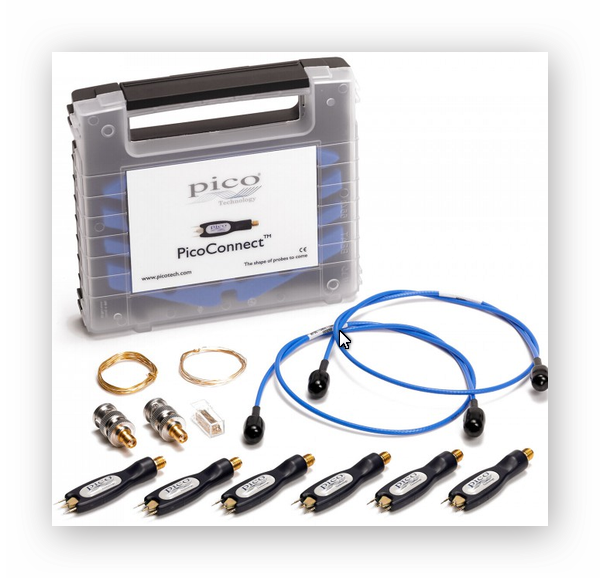 |
PicoConnect probes are specified and characterized with a supplied 085 high-performance flexible coaxial cable, with which they achieve market-leading flatness and pulse response. The innovative in-PCB coplanar construction (patent pending) guarantees underlying microwave integrity along with mechanical precision, strength and electromagnetic immunity. The passive design is inherently resistant to static discharge and demonstrates no significant overload recovery latency or error. The PicoConnect probes and multi-head probe kits are provided with solder-in accessories in a convenient carry and storage case.
Specifications:
| Model |
911 |
912 |
913 |
914 |
915 |
916 |
| Nominal division ratio |
20:1 |
10:1 |
5:1 |
| Bandwidth (–3 dB) |
> 4 GHz |
> 4 GHz |
> 5 GHz |
| Max. usable data rate (fundamental) |
8 Gb/s |
8 Gb/s |
10 Gb/s |
| Max. usable data rate (3rd harmonic) |
2.6 Gb/s |
2.6 Gb/s |
3.3 Gb/s |
| Max. usable data rate (5th harmonic) |
1.6 Gb/s |
1.6 Gb/s |
2 Gb/s |
| Transition time |
< 87.5 ps |
< 87.5 ps |
< 70 ps |
| Probe tip impedance (nominal) |
960 Ω |
440 Ω |
230 Ω |
| Probe tip capacitance (typical) |
0.3 pF |
| Probe tip capacitance (maximum) |
0.4 pF |
| Accuracy for line Z0 = 40 Ω to 60 Ω[1] |
< ±0.13 dB (±1.6%) |
< ±0.18 dB (±2.1%) |
< ±0.30 dB (±3.4%) |
| Accuracy for line Z0 = 0 Ω to 100 Ω[2] |
< ±0.25 dB (±2.9%) |
< ±0.50 dB (±6.0%) |
< ±0.93 dB (±10.2%) |
| Nominal error for line Z0 = 75 Ω[3] |
< –0.17 dB (–1.9%) |
< –0.26 dB (–2.9%) |
< –0.54 dB (–6.0%) |
| Continuous voltage[4] |
14 V AC RMS |
14 V RMS |
10 V AC RMS |
10 V RMS |
8 V AC RMS |
8 V RMS |
| DC blocking voltage (max.) |
50 V DC |
- |
50 V DC |
- |
50 V DC |
- |
| Peak voltage[5,6] |
< 150 V |
| Pulse width at peak voltage |
< 500 ns |
| Mark:space at peak voltage |
< 1:120 (0.8%) |
< 1:230 (0.4%) |
< 1:360 (0.3%) |
| Coupling[4] |
AC |
DC |
AC |
DC |
AC |
DC |
| Low-frequency cut-off (–3 dB) |
40 kHz |
- |
80 kHz |
- |
150 kHz |
- |
| Pulse /eye droop |
> 50 ns / % |
- |
> 20 ns / % |
- |
> 10 ns / % |
- |
| Flatness (±0.5 dB) |
120 kHz to 2 GHz |
DC to 2 GHz |
240 kHz to 2 GHz |
DC to 2 GHz |
450 kHz to 2 GHz |
DC to 2 GHz |
Output impedance[6]
(for test node impedance 50 Ω) |
717 Ω |
245 Ω |
203 Ω |
| Additive voltage noise @ 23 °C |
3.4 nV/√Hz |
2.0 nV/√Hz |
1.7 nV/√Hz |
| Environment |
| Operating temperature range |
0 to 50°C |
| Storage temperature range |
–20 to 70°C |
| Temperature range for stated specifications |
15 to 40°C |
| Operating humidity range |
5% to 80% RH non-condensing |
| Storage humidity range |
5% to 95% RH non-condensing |
| Altitude range |
up to 2000 m |
| Pollution degree |
2 |
| Safety approvals |
EN61010-031:2002 A1 2008 safety requirements for hand-held probe assemblies for electrical measurement and test |
| EMC approvals |
Not applicable |
| Environmental approvals |
2012/19/EU - Waste Electrical and Electronic Equipment 2011/65/EU - Restriction of use of certain Hazardous Substances in Electrical and Electronic Equipment |
| General |
| Output connector (probe head) |
SMA(f |
| Supplied cable |
60 cm SMA(m-m) precision unsleeved high-flex 085 microwave coaxial cable (unsleeved and 30 cm options also available) |
| Supplied accessories |
Pack of replacement probe tips; two coils of solder-in gold-plated wire; SMA-to-BNC adaptor (with RF, microwave and pulse models only) |
| Dimensions (probe head) |
68 x 19 x 11 mm |
| Nominal probe tip pitch |
5 mm |
| Weight |
5 g
|
All specifications are subject to change without notice.
Note 1: Line impedance range representative of most common 50 Ω (100 Ω differential) and 45 Ω (90 Ω differential) lines ± 20% mismatch.
Note 2: Line impedance range covers all typical transmission line or test node impedances in the range 0 Ω to 100 Ω (200 Ω differential).
Note 3: CAUTION: When using AC coupled probes, to avoid damage to the connected instrument ensure that it can withstand transient voltage equal to the DC bias of the test node divided by the nominal probe ratio.
Note 4: Typically it will be possible to scale results at the connected instrument to correct for this small nominal error.
Note 5: WARNING: For peak voltage above 46.7 V, to ensure that touch current lies within acceptable limits of EN61010: 2010, pulse or burst width must not exceed 500 ns and pulse mark:space must remain below 2%.
Note 6: CAUTION: To avoid damage to the probe, RMS voltage over the pulse period must remain within specified probe rating.
Note 7: Probes having unmatched output impedance will not absorb pulse aberrations that reflect off mismatch at the connected instrument input. Pulse fidelity and flatness are therefore more dependent on good instrument match.
PLEASE CONTACT US TO CONFIGURE AND ORDER YOUR PROBE
| sku |
product # |
description |
price |
| PQ067 |
PicoConnect 910 Kit |
PicoConnect 910 Kit: all six 4 to 5 GHz RF, microwave and pulse probe head models with cable |
|
| TA274 |
PicoConnect 911 |
PicoConnect 911 20:1 AC-coupled 4 GHz RF, microwave and pulse passive probe |
|
| TA275 |
PicoConnect 912 |
PicoConnect 912 20:1 DC-coupled 4 GHz RF, microwave and pulse passive probe |
|
| TA278 |
PicoConnect 913 |
PicoConnect 913 10:1 AC-coupled 4 GHz RF, microwave and pulse passive probe |
|
| TA279 |
PicoConnect 914 |
PicoConnect 914 10:1 DC-coupled 4 GHz RF, microwave and pulse passive probe |
|
| TA282 |
PicoConnect 915 |
PicoConnect 915 5:1 AC-coupled 5 GHz RF, microwave and pulse passive probe |
|
| TA283 |
PicoConnect 916 |
PicoConnect 916 5:1 DC-coupled 5 GHz RF, microwave and pulse passive probe |
|
|
|
|
|
|


