|
The PP218 current clamp is ideal for use with the ADC-212, 3000, 4000 or 5000 Series Scopes for measuring currents between 10mA and 60A. This enables the scope to display current waveforms for fuel injectors and fuel pumps (see waveforms below).
The current clamp has two calibration settings, set by a slider switch on the handle of the probe.
- 1mV/10mA (100mV=1A): use this for testing currents up to 20A.
- 1mV/100mA (10mV=1A): use this for testing current up to 60A.
In use there is no need to break into the circuit or disturb the isolation as the opening jaws simply clamp around the current carrying conductor. No electrical contact is required.
|
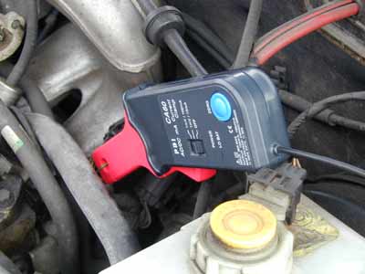
Connecting the PP218 current clamp
|
The current clamp is supplied with 4mm (banana)plug type connectors so can not be plugged directly into the scope. To connect to the scope we recommend the use of the TA000 BNC to 4mm test lead, alternatively the MI078 BNC to 4mm plug adaptor can also be used.
Once connected to the scope switch the current clamp on (green LED should light) and then clamp the jaws around the current carrying conductor (as pictured).
|
 |
Using the PP218 current clamp with PicoScope
The current clamp has two calibrated settings:
- 1mV/10mA (100mV=1A): use this for testing currents up to 20A.
- 1mV/100mA (10mV=1A): use this for testing current up to 60A.
A quick check that the clamp is working can be done by measuring the current drawn when a cars headlamps are switched on. To do this start PicoScope and select 1mV/10mA range (DC coupled) on either the scope or the meter. Connect the clamp around one of the wires to the headlamps. With nothing on the car switched on the reading on PicoScope should be near 0mV. Now swich the headlamps on, the reading should jump up a few mV (100mV per amp of current drawn). If the reading in fact jumps down, dont worry - current clamps are directional, just reverse the clamp on the conductor.
|
Using PicoScope it is easy to scale the output from the clamp from mV to Amps. First select Settings | Custom Ranges from the drop down menu and click on the ADD button.
Next fill in the scaling information. The custom settings on the right, scales the mV output from the current clamp in the 1mV/100mA setting. The output from Picoscope will be between the range of 0 and 60 amps.

|
The Custom range on the left, scales the mV output from the current clamp in the 1mV/10mA setting. Picoscope will show the output from the current clamp within the range of 0 to 20 amps.
More information on scaling can be found in PicoScopes online manual.
When you have filled in the scaling information press the OK button (twice) to return to the main menu. Now select File | Save Settings to save your custom range. This custom range now appears in the drop down list of voltage ranges (see examples below).
|
Injector current waveform
The waveform below shows the current waveform for a fuel injector. The waveform shows two stages. The first stage (0 to 1.2mS) shows a small amount of current being drawn, where the injector has been switched by the ECU but the solenoid is charging and hasn't been fired. After this small delay an increase in current can be seen. This is the solenoid actually firing and fuel being injected into the engine.
Fuel pump current
The screenshot below shows a captured current waveform from a fuel pump. The waveform can be seen to have an AC ripple due to the switching between different communtators in the motor. This can be seen to repeat every 8 cycles. A fault with one of the windings or brushes will be shown by the current drawn for one period of the waveform being reduced significantly.
Buy the PP218 Clamp online:
You will also need this adaptor to connect to a BNC Scope [MI078]:
|