|
|
|||
| Log In | |||
|
| |||
|
| |||
| |||
| |||


CAN bus (Controller Area Network) is a serial data standard originally developed in the 1980s by Robert Bosch GmbH for use in automotive applications. Today it is also widely used in industrial process control and aerospace applications. It allows microcontrollers and electronic devices to communicate with each other without using a host computer and provides fast and reliable data transfer in electrically noisy environments at low cost and with minimal wiring. CAN employs differential signaling to provide a high level of immunity to electrical noise. In 1991 Bosch published the specification for CAN 2.0, which details two formats:
In 1993 ISO (International Organization for Standardization) released the CAN standard ISO 11898, which was later restructured into three parts:
Bosch subsequently released CAN FD 1.0 or CAN with Flexible Data-rate, which was incorporated into ISO 11898-1:2015. This specification allows for increased data lengths as well as optionally switching to a faster bit rate after the arbitration is decided. CAN FD is reverse-compatible with existing CAN 2.0 networks, so new CAN FD devices can coexist on the same network with existing CAN devices.
Arbitration CAN data is sent in Frames starting with a dominant 0 followed by an Identifier, which forms the basis of arbitration (Priority) where two or more nodes attempt to transmit at the same time. Each node is assigned an Identifier which can be 11 bits (CAN 2.0A) or 29 bits (CAN 2.0B) in length. The table shows three nodes attempting to transmit at the same time, each starting with dominant 0s. When a node transmits a recessive 1 but sees that the bus remains at dominant 0, it realizes there is a contention and ceases to transmit and waits for the next opportunity to transmit. In this way the node with the lowest value ID wins arbitration and is given priority to transmit the rest of the frame.  Frames
CAN has four frame types:
The RTR bit (Remote transmission request) determines between data frames (0) and remote frames (1) A CAN network can be configured to work with two different frame formats: the base frame format (CAN 2.0A & CAN 2.0B) which supports 11-bit identifiers, and the extended frame format (CAN2.0B only) which supports 29-bit identifiers by allowing the addition of an 18-bit identifier extension. An identifier extension bit (IDE) determines if the 18-bit ID extension is being used. The table shows the format for a CAN Data Frame with Base Format (11-bit) with no bit stuffing The Data Length Code indicates the length of data in bytes; in this case 1 byte. CRC stands for cyclic redundancy check, which is used for error detection. Ack slot bit – All nodes that receive a frame without finding any errors transmit a dominant 0, which overrides a recessive 1 sent by the transmitter. If the transmitter detects a recessive 1, it knows that the frame was not received correctly. End of frame is confirmed by the transmission of 7 recessive 1s. 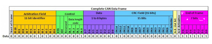
Bit-stuffing
To ensure enough transitions to maintain synchronization, a bit of opposite polarity is inserted after five consecutive bits of the same polarity. Bit-stuffing does not occur during the CRC delimiter, ACK field and end of frame. In the fields where bit-stuffing is used, six consecutive bits of the same type (000000 or 111111) are considered an error and an active error flag consisting of six consecutive dominant bits can be transmitted by a node when an error has been detected.
Differences in protocol between CAN and CAN FD
The table shows the structure of a CAN FD frame. Arbitration and the use of Base and Extended frame formats are identical in both classical CAN and CAN FD. CAN FD does not use remote frames and so the RTR bit used in CAN is redundant and termed SRR Substitute Remote Request, and is recessive. The IDE bit is used in the same way. The reserve bit in CAN now becomes the FDF bit (Flexible Data Format) and is a dominant 0 to indicate that the frame is in CAN FD format. Frames sent in classical CAN format are indicated with a recessive 1. Next is a reserve bit for future use. Then comes the BRS bit (Bit Rate Switch). If BRS is sent dominant, the bit rate remains the same across the whole frame. If BRS is recessive, a higher bit rate will be transmitted after this bit up to and including the CRC delimiter. The ESI bit (Error State Indicator) is a dominant transmission for error active, and recessive transmission for error passive. 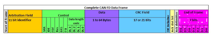
CAN FD CRC field
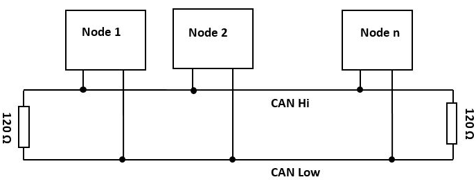
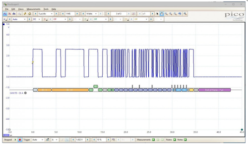
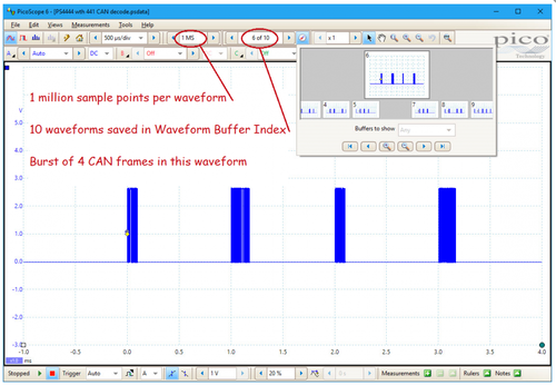
Because of the longer data lengths with CAN FD, more bits are required for the CRC check. If the frame holds 16 bytes or less, a CRC with 17 bits is used; and if the CAN frame holds 20 bytes or more, a CRC with 21 bits is used. After the CRC field the Ack and end of frame structure is the same as with classical CAN. CAN bus debugging Errors can occur due to inductors, coils and power devices which can cause large voltage spikes, noise and ringing. An increasing number of embedded computers and devices are being added to automobile CAN buses and as more nodes are added the available bus time becomes more occupied. When the traffic reaches around 40% of the bus time, errors can start to occur. At this point an oscilloscope may be required to debug the network. To monitor and find faults on a CAN bus it is important to have an oscilloscope with deep memory to capture a large time window with multiple frames of data. The instrument can then process the entire acquired waveform and then zoom in to analyze the data packets. We recommend that the instrument has a bandwidth of ten times the CAN baud rate, to analyze rise times and any fault conditions. Step one – probing CAN is a differential signal, CAN Low being the inverse of CAN High. Viewing the difference between the two removes any common-mode interference encountered by the signal during transmission. Best results will be achieved by acquiring the signal difference between CAN Low and CAN High using a differential probe or a differential input oscilloscope such as the PicoScope 4444. The signal can still be acquired using a single-ended probe connected to either CAN Low or CAN high, but any common-mode noise will be displayed and may cause errors in decoding on the oscilloscope which would not affect the CAN receiver.[CAN bus waveform captured with PicoScope]
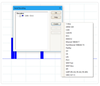
If Graph is selected, a color-coded trace will appear in the graph display, time-correlated with the acquired data. If Table is selected, all the data will be presented in a table format. There are several useful features available with the table:
 Summary CAN and CAN FD decode is a standard feature in the PicoScope software and can be used with all real-time PicoScope oscilloscopes. |
||||||||||||||||||