


|
|
|||
 |
|||
| Log In | |||
|
|||
|
|||
|
| |||
|
|||
| |||
|
|||
| |||
|
|||
|
| |||
|
|||
| |||
|
|||
| |||




With the launch of the new PicoScope 4000 Series automotive scopes came the term Floating Inputs. While this feature is a first for Pico and the automotive market, what does it really mean for the technician and how can this feature best be utilized in our day-to-day activities? The term floating refers to the fact that the input channels no longer share a common ground as with the previous 4000 Series scopes. Each input channel is required to be grounded independently and can be connected to a reference voltage 30 V above or below vehicle ground. Ground reference connections can therefore float ±30 V from vehicle ground. The examples below best describe how the architecture of the new scope differs from the previous generation. 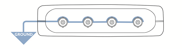 Previous PicoScope 4000 Series scopes share a common ground between all channels 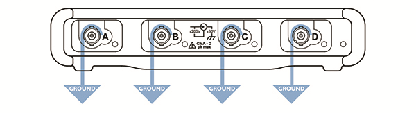 New PicoScope 4000 Series scope input channels are required to be individually grounded So how does the technician benefit from floating inputs? Voltage drop test with one channelThink of the new 4000 Series scope as four separate multimeters in one sealed unit. Each multimeter represents 1 x input channel with 2 x test leads (signal and ground lead). Now think about how we use a multimeter for voltage drop measurements on a starter motor positive cable, connecting the signal lead and ground lead to either end of the starter cable and operating the starter motor (both test leads are above 0 V). The new 4000 Series scope can carry out the exact same test with one channel! Previously we needed 2 x channels and a math channel to subtract one channel from another to obtain the voltage drop value. 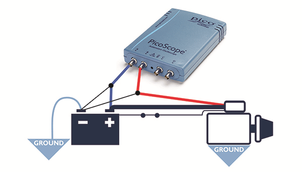 Previous model required 2 channels and a Maths Channel "A-B" to calculate voltage drop 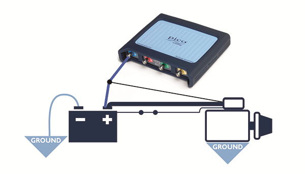 New PicoScope 4000 Series require only 1 channel to calculate voltage drop Reverse-polarity actuators with one channelThrottle motors are just one example where reverse polarity features heavily in automotive applications. The image below demonstrates the operation of a throttle motor and how the polarity of the measured voltage changes during the transition from idle to Wide Open Throttle (WOT). The scope test leads are connected across the throttle motor with no reference to vehicle ground. Other channels connected to the scope can be connected to vehicle ground with no effect on our signal or throttle motor operation. 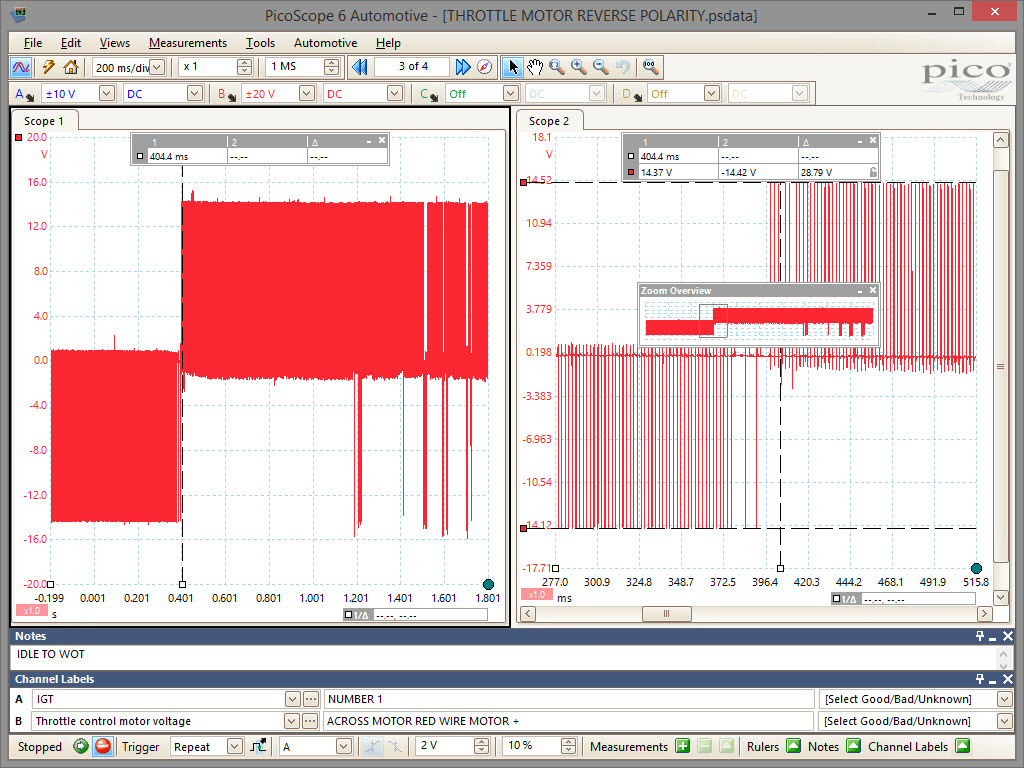 We no longer have to worry about using a ground reference above 0 V as each input channel ground reference is independent of the others. A beneficial side effect is that accidental reverse polarityof battery connections is nothing to be concerned about as the scope will simply respond by displaying –12 V (identical to a multimeter). Measure across components with one channelWideband oxygen sensors utilize a measurement cell generating a voltage of 450 mV between two terminals of their harness connector. Floating inputs will allow the technician to connect across these terminals and directly measure the 450 mV while using the remaining input channels for other measurements (the voltage of the pump cell for example). Using a scope with common ground inputs, our 450 mV would need to be measured using two channels connected to each terminal at the harness connector and referenced to vehicle ground. A math channel would then be used to subtract the measured values of each channel to arrive at 450 mV. 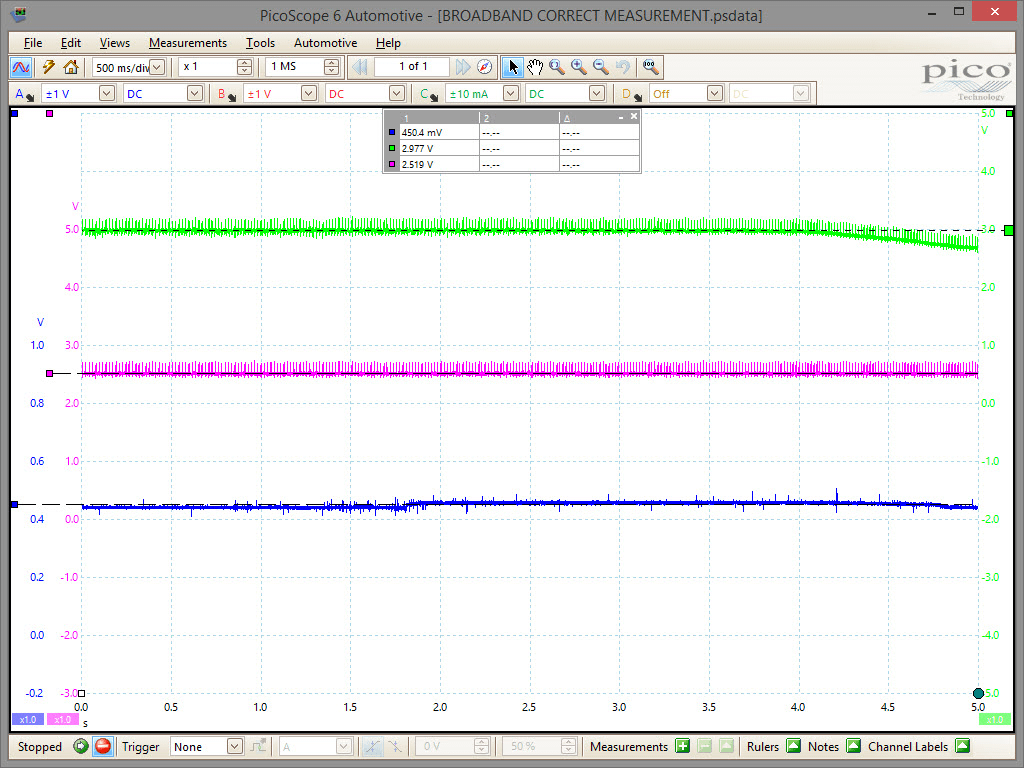 Above, we can see a common ground scope using two channels (green and magenta) measuring terminal 1 and terminal 5 (of our broadband sensor) referenced to vehicle ground, providing values of 2.977 V and 2.519 V. When subtracted, a value of 458 mV is revealed. The floating input scope (blue trace) measures across terminals 1 and 5 of our broadband sensor, and records a similar 450 mV. When not to float the ground inputWhile floating inputs give new flexibility it is important to ensure they are used correctly. The main requirement is that the negative input is not connected to any signal that is more than 30 V away from chassis ground (battery 0 V) otherwise measurement errors may occur (an LED on the front of the scope will light to warn you). Care must be taken on primary ignition and injector measurements where inductive voltage spikes are often much higher than 30 V. Some inductive crankshaft sensors can also exceed 30 V at higher RPMs. The second consideration is that the negative input provides a higher capacitive loading than the positive input. As such the negative input should not be connected to fast changing signals such as CAN Bus, FlexRAY or some crankshaft sensors that may be effected by capacitive loading. ConclusionFloating inputs have allowed the technicians the freedom to measure a variety of circuits with the simplicity of a multimeter without the sacrifice of additional input channels, so extending the range of measurements available while revealing new measurement techniques. |
|||||

 |
 |
|||
|
|
|
 |