The Versatile Scope - Part 1
By Nick Hibberd
Hibtech Auto-Electrical Diagnostics
It's not only on engine management within a vehicle where an oscilloscope delivers interesting finds: you can pretty much back-probe any wire and record a usable trace. You often find circuit operational characteristics that are not available in any OEM manual, and it's this knowledge-building which is absolute gold. However, the only way to get truly proficient with an oscilloscope is to teach yourself, and this requires some investment of your time.
I've compiled a couple of recent investigations which are a world away from ignition or injection and demonstrate the oscilloscope as a versatile fault-finding tool. Any hardened "petrol head" may want to look away now.
BMW X5 Battery Drain
This BMW had a complaint of intermittent no start caused by the vehicle battery discharging. Sometimes it would last two weeks and other times only last two days. The battery had already been replaced, twice, and the alternator overhauled and given a clean bill of health. The garage involved reported that each time the vehicle was checked for parasitic draw, none was found: a nightmare scenario, so where do you start?
BMWs are famous for their long shut-down times and purely from my own experience I expect somewhere between 16 and 18 minutes before sleep mode is reached. This wait-time is a real headache when trying to fault-find because, until you have allowed enough time to expire, you could end up chasing a problem that doesn't exist. Furthermore, start tracing too early by pulling or replacing circuit fuses and you're likely to reset a controller, adding more wait-time. Easy this, isn't it?
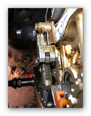
Cut to the fault. Executing a simple parasitic draw test at the battery, I eventually picked up on sporadic surges in current draw that didn't fit with all previous shutdown patterns, with the ammeter recording surges as high as 5 amps. Through different tracing techniques I narrowed the search to the AC system and in particular the interior blower.
interior Blower
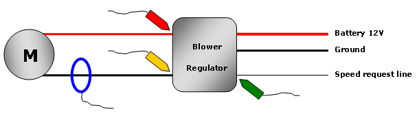
The blower regulator receives constant battery power and relies on a single information line from the heater controller to increase or decrease motor speed. This information arrives at the regulator in the form of a varying DC voltage where 0 V equals full off. At rest the motor receives 12 V permanently and relies on the regulator to vary the ground level applied, thus varying the motor speed.
I hooked up the scope to the blower regulator and set it recording:

To obtain some suitable readings for analysis, Fig.1 was captured during a full speed sweep command. You can walk through the circuit operation starting with the speed request on CHC. As the request voltage increases, the regulator begins to supply a ground path for the motor creating a potential different across it; so the motor starts to turn. The speed request is incremental and likewise is the ground path applied to the motor.

Current flow on CHA follows a good trend as speed request increases, and closer inspection of commutation reveals a seemingly good motor. However, my attention was drawn to the part of the trace when speed was reducing, and current fluctuated as the regulator struggled to maintain a steady ground path. During this erroneous stage the speed request line held steady, which was evidence that the regulator was causing this particular anomaly. This was a real surprise as I didn't hear or feel anything unusual through the air vents, so it was entirely down to the scope for spotting that. Although this shows that the regulator operation is incorrect during normal use, it hasn't given anything conclusive towards our battery drain fault - yet.
An ammeter still monitoring parasitic draw coming straight out of the battery will give me a clear flag when the fault is present. So, hopefully, if the test plan so far has been correct, the scope should record some activity from the blower circuit.
The car was powered down as normal then left to settle. Waiting for a fault to appear can sometimes be a battle of patience, and this problem turned out to be no exception.

It took some time before the vehicle decided to fail. Then the meter reading started to swing high, giving me a clear indication the fault was now present. Fig.2 was subsequently recorded and shows the fault clearly. The ground path from the regulator unit is starting to leak into the motor circuit, allowing a current path through the motor that creates an excessive burden on the battery. If this is happening all night long, that 3.0 diesel lump is going to be very disappointed in the morning. A new blower regulator was installed.
As stated at the outset, the use of an oscilloscope and the interpretation of the display are very educational. I come back to the discovery of "circuit operational characteristics" and its role in knowledge building: you get out what you put in.
Read Nick Hibberd's second fault-finding investigation next month!
|