By Darren Cotton, AVC (UK) Ltd
- Vehicle: BMW Mini
- Year: 2001
- Symptom: Airbag light on and tire pressure monitoring light was also illuminated after valet. A mobile company had already been out to it and their diagnostic tool was not connecting to it.
Preliminary test and Investigation
Using Autologic, I carried out a quick scan; this feature will attempt to connect to every module for that variant. I found that we had no communication for Multiple Restraint System (MRS), Electronic Transmission Management (EGS), Radio (RAD) and Immobiliser (EWS).
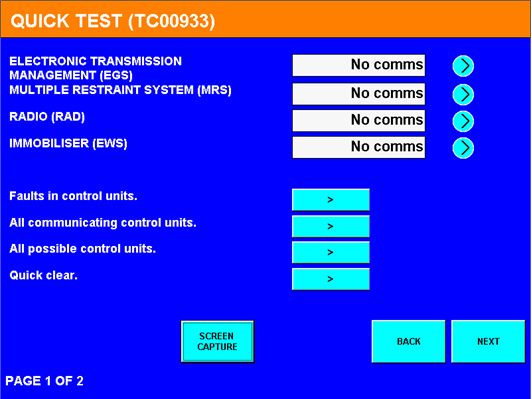
Figure 1: Autologic scan results
Maybe the mobile company’s device was telling the truth but maybe unable to handle the repair. This is obviously why we have warning lights illuminated. The advantage of using a high quality dealer level tool is that you know you can trust the information it is telling you. Keeping in mind the customer is just interested in the Airbag and the TPMS warning lights, but is this just one fault? And where do we start…?
Vehicle started and drove fine, Radio OK, but TPMS (tyre pressure monitoring sensor) function not resetting.
Diagnosis
The vehicle was left with me and I was able to put a diagnostic plan in place. As stated above, the vehicle started and drove fine, the TPMS is a manual reset function and would not reset. I focused on the Multiple Restraint System (MRS) and looked at the schematics of the airbag system, in fact using the BMW Mini wiring diagram system it made it very easy and a plan of attack was put into place.
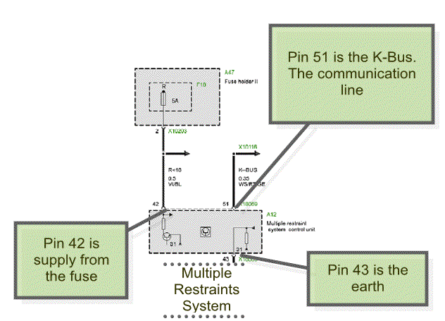
Figure 2: Mini wiring diagram
So I decided to check that the 5 Amp fuse F18 for the MRS, it had a Nominal Battery Voltage (NBV) and was in good order, and the plan was to get access to the MRS module. The module is located under the handbrake lever under the carpet and was not accessible easily, the front seats were removed and the carpet lifted from the rear seats to the front of the vehicle just enough to access the module. With the diagram I was able to check the cavities shown. The supply and earth was in good order.
I wanted to check the communication line as we do have other modules not communicating here, attaching the PicoScope to cavity 51 of the MRS module I was able to see the K–Bus signal; I also located the K–Bus at the O/S/F door sill. Capturing the K–Bus we can see what’s going on here, something was not right. On this Variant the K-BUS wire is White and Red with yellow band (WS/RT/GE).
In Figure 3 below, top and bottom captures are the same, top trace is a zoomed in trace of the lower one. The Green trace is K-BUS at driver’s door sill, and the Red trace is K-BUS at the MRS module cavity 51.
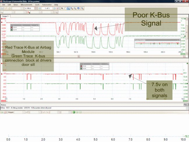
Figure 3: Poor K–Bus signal
The capture above (Figure 3) is one single wire, RED trace is at AIRBAG module and GREEN trace is at Driver’s door sill. Zoomed in, the data being sent was not correct and the input voltage was at 7.5 V this is also incorrect, so now I was getting somewhere, this is our problem and Ijust need to locate the cause…
K–Bus in brief
K–Bus consists of a single copper wire and data transfer is approx. 9.6 kbps (kilobits per second) and is always active when terminal R is switched on. If the bus line is quiet for more than 60 seconds all the control modules that are connected will go into sleep mode. The wire colour is uniform throughout the vehicle, WS/RT/GE (White/Red/Yellow).
Due to the linear structure of the network, K–Bus is available for other modules in the event of a disconnection or failed control unit, Just as the CAN bus, this is referred to as a tree structure with each control unit occupying a branch. The K–Bus provides a diagnostic connection to the control unit connected on those busses. The K–Bus uses only a determined controller to supply B for communication. The voltage level must be above 7 V. The nominal voltage should be close to NBV, in my experience a good working K–Bus is around 13 V.
Figure 4 shows the poor K–Bus signal zoomed in.
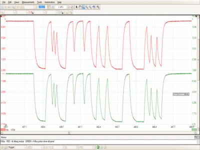
Figure 4: Poor K–Bus signal zoomed in
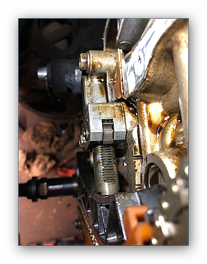
Studying the wiring diagram it led me to the BCM which on this variant is located in the driver’s side foot–well. Upon removing the module I found water ingress and the wiring harness was soaked… Unplugging the harness the cause was very clear. Corrosion to the terminals at the BCM was so bad that as I unplugged it the pin had broken off.
Figure 5 shows the BCM with the broken pin.
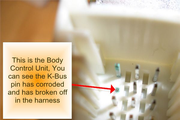
Figure 5: BCM with broken pin
So in a real world this needs a new BCM and a wiring harness, but this is a sales car and they do not spend money, so I came up with a plan.
The fix
I opened the BCM and followed the pin back and soldered a wire to the good part inside the BCM.
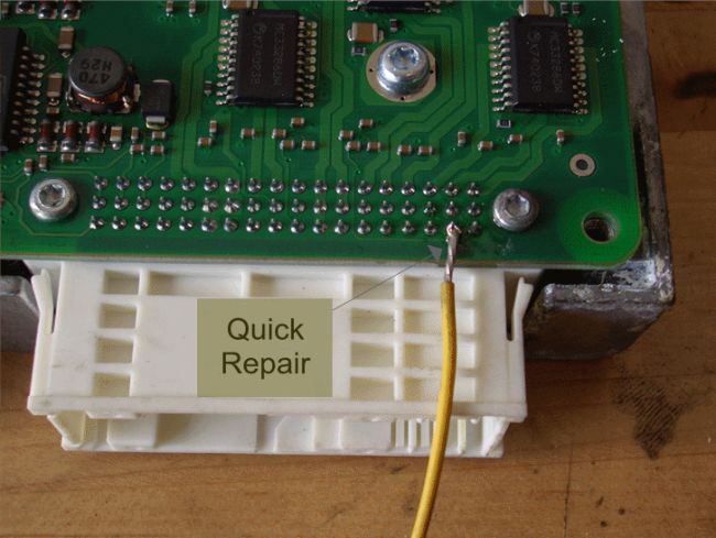
Figure 6: Fixing the problem
I attached the wire to the other side of the multi–plug. After refitting the BCM I carried out a global scan which gave me full communication to all modules, the TPMS reset and all is looking good. Attached the PicoScope to the K-BUS again just for good measure… Which confirmed the repair was a success.
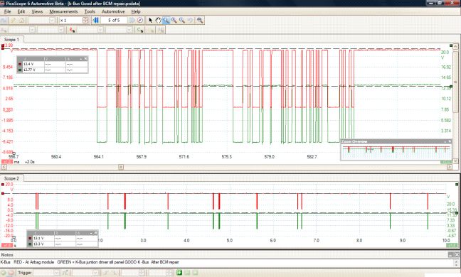
Figure 7: Good K–Bus signal after the repair
Conclusion
Maybe the mobile company who looked at this first are looking for the quick repairs or do not have the confidence of the repair, once the system is understood the process becomes easier and it goes to show that one device is just not enough. The PicoScope in this situation definitely helped in the diagnosis, hard to prove otherwise.
|