Vehicle details:
- 1995 Mercedes W140 S-Class
- M119 V8 Engine
Background information
The Mercedes W140 S-Class V8 engine had developed an intermittent misfiring fault. The misfiring could be observed during idle speed when the engine was warm - however it was not a serious issue. Within a month it became apparent that as the engine coolant temperature reached 60 °C, the 'intermittent' fault became permanent. At this stage the car was still drivable, but had significantly less performance than expected and higher fuel consumption than normal. The engine has a Bosch LH-Jetronic ('Luftmasse-Hitzdraht') injection control with hot wire air mass meter, 2 ignition coils and 2 distributors. The ignition is controlled by a separate EZL ('Elektronische Zündanlage') i.e. ignition control module. There were no DTCs stored.
The investigation
As an initial test, the injectors were cut off one by one in order to determine the cylinders at fault. It was found that with cylinders 1, 4, 6, and 7 cut off, the idle speed did not change. These cylinders are all fed by the distributor mounted on the right cylinder bank.
Injector 6 was double checked with the scope and was found working but unsettled. The injector open time changed quickly (±1 ms) and in turn the engine idle speed also changed:

The king lead was checked and showed two typical waveforms:
 
The spark plug leads were then checked at cylinders four and seven, and the kV was found too low and unstable returning waveforms such as the two below:
 
The primary ignition was measured and compared to the king lead. The primary voltage wave (Ch A) looked normal, but there were abnormal signals on the king lead (Ch B). Here is an example of a good waveform:

Every three or four firings the voltage was jumping in the same manner as when the secondary kV was measured at the spark plugs previously. In addition the engine was juddering in the same manner as the following unstable waveform:

However, the primary current was showing normal signals:

The solution
The first step to solving this issue was to replace all the spark plugs. This was done as they were all close to their 25000 km life span. In addition to new spark plugs, one suppressor with a new HV (High Voltage) lead was replaced temporarily. However, neither change solved or improved the problem we were experiencing. Through a process of elimination, the problem could now be identified as being with either: the coil, the distributor, or the ignition control module (EZL).
The interference at the primary ignition was misleading when viewing the diagnostics results. This was proven because the temporary connection of a good coil did not change the recordings. Due to this, we moved our attention on to the distributor.
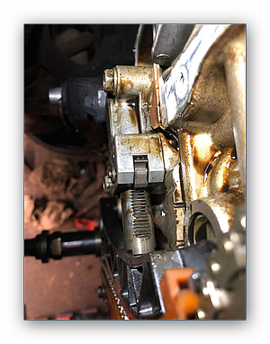
Only once the distributor was removed, was it possible to see where the high voltages had broken through on the back side and jumped against the engine block. This resulted in all energy being lost under the cap, and nothing being delivered to the plugs. The problem had started when the misfiring at idle speed was first noticed. Various small cracks in the casing, starting from the distributor centre pin, were growing in length over a short time. The distributor was later cut for investigation to identify that cause of the problem.
The high voltage shot out at the glass fibre 1 kilohm resistor and made a conical hole in the casing.

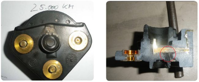
In the above left image, the distributor is shown still in place; you can clearly see the discolouration in the middle. Both the centre and right images show the micro cracks.
The left image below shows the rear of the distributor, revealing the outlet for the high voltage, while the right image shows the distributor cut in half, displaying the exit taken by the high voltage at the resistor.
The result
Once the distributor had been replaced the waveforms showed the expected signals.
The conclusion
The capture of the waveforms did not take long, but the interference on the primary side was misleading, due to the ground signal being disturbed by the high voltage going into the engine block. Other than that no part was unnecessarily replaced and the fault was found even without stored DTCs.
The reason the distributor was not considered to be at fault earlier in the investigation was because it was almost new, having been replaced in 2007 and only been used for 25000 km.
|