By using a Virtual CAN Bus, we separate the control task from other tasks. The distributed embedded control system can be developed using standard CAN Controllers and transceivers in a traditional way with well proven tools.
Other tasks such as encryption, transmitter authentication, re-flashing, etc. can be developed by experts in these fields and carried out by using other protocols. With modern technology, the different tasks can run in parallel and simultaneously communicate on the same physical layer.
It is a great advantage to separate the control problems from other problems. The control problem can be solved once and for all by the control experts and other problems by experts in their respective technology fields.
The customer complained of an EBS braking fault which occurred intermittently. When the fault occurred then the EBS light would illuminate on the display and the EBS function would revert to conventional braking. This fault had been a problem for some time.
When the vehicle's electronic systems were interrogated the same faults were always apparent:
EBS ECU under voltage fault code for the power supply to the ECU.
Engine ECU over voltage fault code for the power supply to the ECU.
The driver also reported that the radio fuse would blow regularly and that the interior lights would dim momentarily.
The vehicle was subjected to a variety of electrical tests to try and determine if the wiring harness or ECUs were damaged. It was noted that the starter motor and alternator both functioned correctly and that the power supply to the components measured at 24V. Further detailed inspections of harnesses on the chassis and in the cab provided no lead as to the under-voltage and over-voltage situations occurring simultaneously on both ECUs.
Diagnosis
The DAF UK technical department were requested to assist. During their diagnosis of the vehicle, the vehicle's ECUs were monitored with the PicoScope oscilloscope for power fluctuations. During a road test the oscilloscope picked up anomalies in voltage supply which occurred for just a few milliseconds.
The trace below identifies a momentary voltage and current spike detected at the power supply to cab and to the Engine ECU for a period of 60 ms, but essentially it was noted that this occurred when the vehicle started to pull away from a rough road lay-by
Blue – Current draw on main power to cab
Orange – Current at the battery bridge
Green – UPEC wake up voltage
Red – UPEC battery feed
This unusual fluctuation led the diagnosing engineer to investigate further, particularly the vibration on the power supply waveform. The driver was asked to drive in a variety of load related situations and the technical engineer monitored the scope for anomalies. As the vehicle slowed down in top gear full throttle was applied causing the engine to labour creating symmetrical spikes on the current draw into the cab as shown below.
The x axis is divided by 20 ms divisions and the spikes are repeated at a regular frequency of circa 5 ms.
Blue – Current draw on main power to cab
Orange – Current at the battery bridge
Green – UPEC wake up voltage
Red – UPEC battery feed
At this point no fault had yet occurred but it could clearly be seen that a symmetrical resonance was creating a power supply issue.
Further testing found that when the exhaust brake was applied with the service brake, then the following spikes were created. On this occasion the voltage to the engine ECU spiked in time to the current spike of the main cab supply.
The voltage to the engine ECU exceeded the set range of the oscilloscope and was in excess of 50 volts. The current draw into the cab momentarily exceeded 50 amps.
Blue – Current draw on main power to cab
Orange – Current at the battery bridge
Green – Engine ECU wake up voltage
Red – Engine ECU battery feed
Whilst the vehicle was being inspected and this set of waveforms being captured in the workshop, it was noticed that at idle the interior lights of the cab started to pulsate slightly.
The below trace shown is for a period of one second only and it clearly shows the voltages to engine ECU and EBS ECU spiking in time with the interior lights pulsating..
Blue – Current draw on main power to cab
Orange – EBS voltage
Green – Current draw through relay G126
Red – Engine ECU battery feed
The fault
It was determined that a main power supply anomaly feeding the cab was the cause. It was known that earlier investigations had ruled out the starter motor, alternator and the main harness to the cab. Therefore the battery cables were manipulated whilst the oscilloscope continued to record the voltage spikes in time with the dimming interior lights. When the battery bridge cable was disturbed the waveform settled to a linear output as would normally be expected.
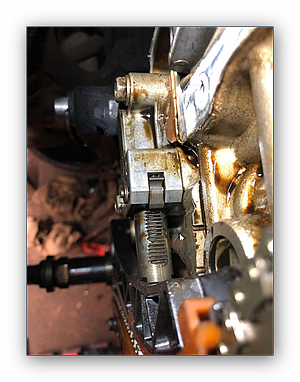
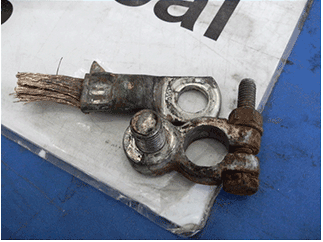
Close inspection of the battery bridge cable found a cracked solder joint between the cable and the battery clamp.
Conclusion
The oscilloscope allowed for multiple channel monitoring and gave graphical depiction of the unfolding problem that could be detected and analysed. The clues from the symmetrical waveforms and the timing of the natural resonance from the engine led to the investigation concentrating on a poor main power supply connection. Systematic manipulation of each of the main battery cables whilst observing the PicoScope traces allowed for immediate response of the waveform once the problem area was disturbed.
Repair
Replacement of the battery bridge cable restored a guaranteed linear voltage supply to the vehicle.