How to connect the oscilloscope when dual-trace testing :-
CAN High and CAN Low
The CANbus scope provides advanced analysis for automotive diagnostics. Plug one BNC Test Lead onto Channel A of the oscilloscope and the other BNC Test Lead onto Channel B. Connect a crocodile clip onto each of the black (Ground) moulded connectors on the BNC Test Leads, and attach them both to the Vehicle Battery -Ve terminal or a good ground point on the chassis. Attach one of the test probes to each of the red moulded connectors on the BNC Test Leads. Using the Vehicle Tech Manual, identify the CAN-H and CAN-L pins at an accessible point on the CAN network. (Usually available at the multi-way connector at each ECU on the network.) Carefully probe the back of the multi-way connector, using Ch A for CAN-H and Ch B for CAN-L. Alternatively, use the Manufacturers Break Out Box.Pressing the spacebar on the PC will enable live data to be viewed. Vehicle ignition may need to be switched on. The CAN-H and CAN-L waveforms will now appear on the screen, as shown below:
VDB (CAN-H & CAN-L) Waveform notes
In this display, we can verify that data is being continuously exchanged along the CANbus, and it is possible to check that the pk to pk voltage levels are correct, and that a signal is present on both CAN lines. CAN uses a differential signal, and the signal on one line should be a coincident mirror image of the data on the other line. The usual reason for examining the CAN signals is where a CAN fault has been indicated by OBD, or to check the CAN connection to a suspected faulty CAN node. (ECU) The Vehicle Manufacturers manual should be referred to for precise waveform parameters.
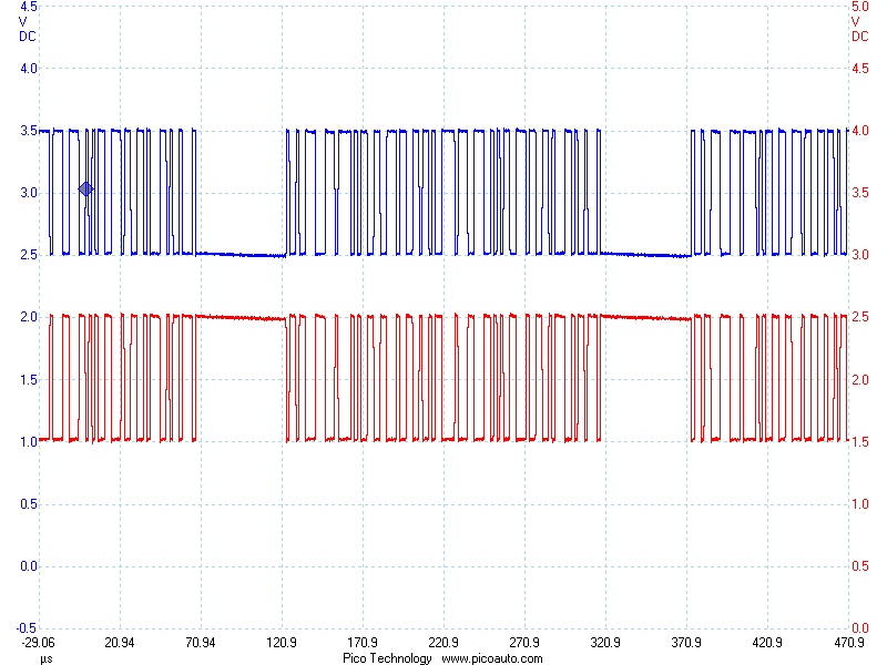
The following CAN data is captured on a much faster timebase and allows the individual state changes to be viewed. This enables the mirror image nature of the signals, and the coincidence of the edges to be verified.
Typical CAN-H and CAN-L waveforms in detail

Here we can see clearly that the signals are equal and opposite, and that they are of the same amplitude. The edges are clean and coincident with each other. This shows that the VDB (CANbus) is enabling communication between the nodes and the CAN controller unit. This test effectively verifies the integrity of the bus at this point in the CAN network, and if a particular ECU (node) is not responding correctly, the fault is likely to be the ECU itself. The rest of the bus should work correctly.
It may be necessary to check the condition of the signals present at the connector of each of the ECUs on the CAN Network, as a final check. The data at each node will always be the same on the same bus. Remember that much of the data on the VDB is safety critical, so DO NOT use insulation piercing probes on VDB (CANbus) lines!
CANbus is a serial communication system used on many motor vehicles to connect individual systems and sensors, as an alternative to conventional multi-wire looms.
It is an acronym for Controller Area Network. It is becoming increasingly common on passenger cars and commercial vehicles.
Advantages include significant weight savings, reliability, ease of manufacture, and increased options for On-Board Diagnostics.
Disadvantages include increased cost, and the need for some specialised knowledge when servicing and repairing the vehicle.
Most motor vehicle CAN networks operate at a bus speed of 250KB/s or 500KB/s, although systems are available operating at up to 1MHz.
The heart of a CANbus is the CAN controller. This is connected to all the components (Nodes) on the network via the CAN-H and CAN-L wires. The signal is differential, ie each of the CAN lines is referenced to the other line, not vehicle ground. This has significant advantages from the point of view of noise rejection when used in electrically noisy environments like motor vehicles. Each network node has a unique identifier. Since the ECU's on the bus are effectively in parallel, all the nodes see all of the data, all of the time. A node only responds when it detects its own identifier. For example, when the ABS ECU sends the command to activate the ABS unit, it responds accordingly, but the rest of the network will ignore the command. Individual nodes can be removed from the network, without affecting the other nodes.
Since many different vehicle components may share the same bus hardware, it is important that available CANbus bandwidth is allocated to the most safety critical systems first. Nodes are usually assigned to one of a number of priority levels. For example, engine controls, brakes and airbags are of the utmost importance from a safety viewpoint, and commands to activate these systems are given highest priority (1) and will be actioned before less critical ones. Audio and navigation devices are often medium (2) priority, and simple activation of lighting may be lowest priority (3). The latest vehicles use up to 3 separate CAN networks, usually of different speeds connected together by gateways. For example, engine management functions may be on a high speed bus at 500KB/s and chassis systems run on a 250KB/s CAN bus. House keeping functions; e.g. lights, ICE, satnav, mirrors, etc are on a low speed bus which may only have one single line often referred to as LIN bus. The data on one of the 3 networks is available to the other 2 networks via gateways to enable, for example, the transmission to get data from the engine management system and viceversa.
A process known as arbitration decides the priority of any messages. In practice, to the user, all actions appear to be immediate.
CANbus is becoming increasingly common on todays vehicles, and will become more common as the technology matures and reduces in cost.
Interested in Serial Automotive BUS, see this excellent white paper on
CAN, CAN FD, FlexRay, Lin & BroadR-Reach Link here....
Document related to CanBus on Aircraft.... Mobile Ready (Couresy of aerospacetestinginternational.com)
Interested in more CAN BUS product details - See our pages for Kvaser and Warwick Controls
Excellent CAN Protocol Tutorial created by Kvaser
Pico Video covering CANBus Physical Layer
|