|
|
|||
| Log In | |||
|
| |||
| |||
| |||
| |||
|
| |||
| |||
| |||
| |||


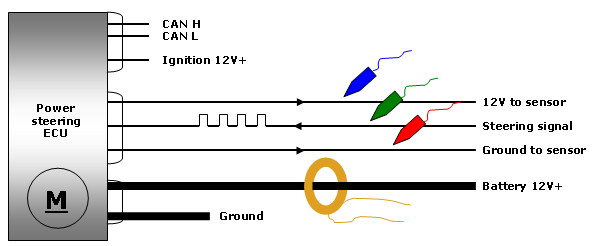
About a month later I returned to car after another complaint of the steering going heavy, and the problem was getting more frequent. Road-testing the car this time, I did manage to see the complaint: without warning the steering suddenly bogged. Keeping one eye on the scan tool's serial data, it was difficult to spot what was dropping out due to its refresh rate and the lack of a data record. More importantly, still no DTCs. There are some initial observations. The scan tool never lost communication, which suggests that the power supplies, CAN lines, and the ECU were functional during the fault event. And with no DTCs logged at any time, this suggests that the ECU was perhaps only responding to conditions it deemed as normal. A control unit's conditional response should always be considered with a no-DTC situation: it doesn't think there's anything wrong. This system is common to the VAG small model range and the key influence dictating steering assist comes from a steering sensor.
With the steering sensor playing such a critical role, the test plan should start there. The scope was hooked up to the steering sensor and pump current draw to see the cause/effect relationship in more detail.
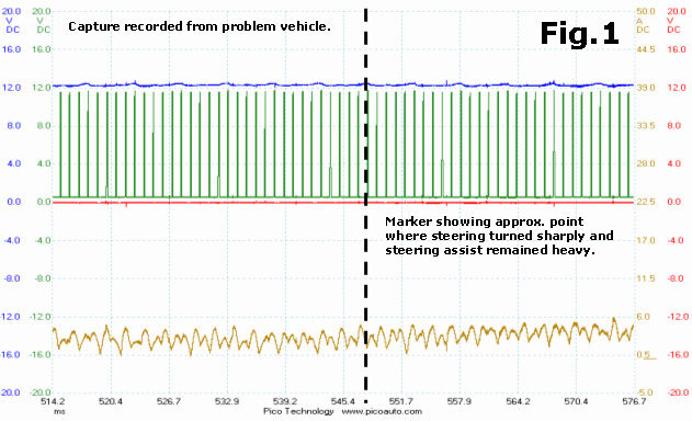
In Fig.1 we can see that there is no significant change in sensor pulse width in response to actual steering wheel rotation: this is a problem. If the ECU doesn't see the sensor react, it follows that no change in pump command will be given. From the capture we can also determine what is not contributing to the fault. We see a good power supply remaining throughout, with the signal line not compromised in any way. Cable continuity can also be eliminated, since power must be arriving at the sensor for a signal to be transmitted, and this signal in turn must be arriving at the ECU since there are no faults reported by the controller. So far, the system is working as normal and merely waiting for the sensor to provide steering information.
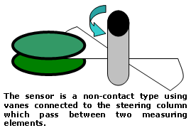
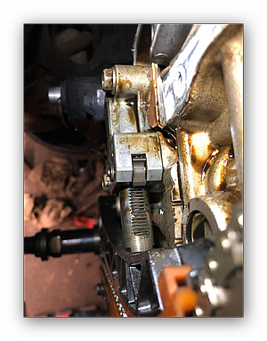
The fault can therefore be localised to the sensor or its measuring principle. The sensor is mounted at the base of the steering column in the engine bay. The sensor was removed and inspected, and showed no visible signs of fouling. With the help of a mirror you can also inspect the vanes inside the column making sure all are present and securely fixed. Also with the sensor removed, a static test can be done by manually passing a metal object through the sensor's field and monitoring its response: sure enough, the signal line didn't alter. This problem is a dud sensor, and it's a problem masked by the fact that the sensor is still capable of producing a valid signal line, just not the correct signal. We come back to a control unit's conditional response. A no-DTC situation can be frustrating, and although it may seem unhelpful, can be used to advantage and should rightfully be considered as part of the fault-find.
Electric power steering has been with us a long time now "...adding enhanced user comfort to the driving experience..." as I heard one sales pitch describe it. Others might argue that it's just more to go wrong. PicoScope data files
|
||||||||