


|
|
|||
| Log In | |||
|
| |||
|
| |||
| |||
| |||
| |||


PicoScope 6000E Series ultra-deep-memory oscilloscopes
Typical applications
Best-in-class bandwidth, sampling rate and memory depth
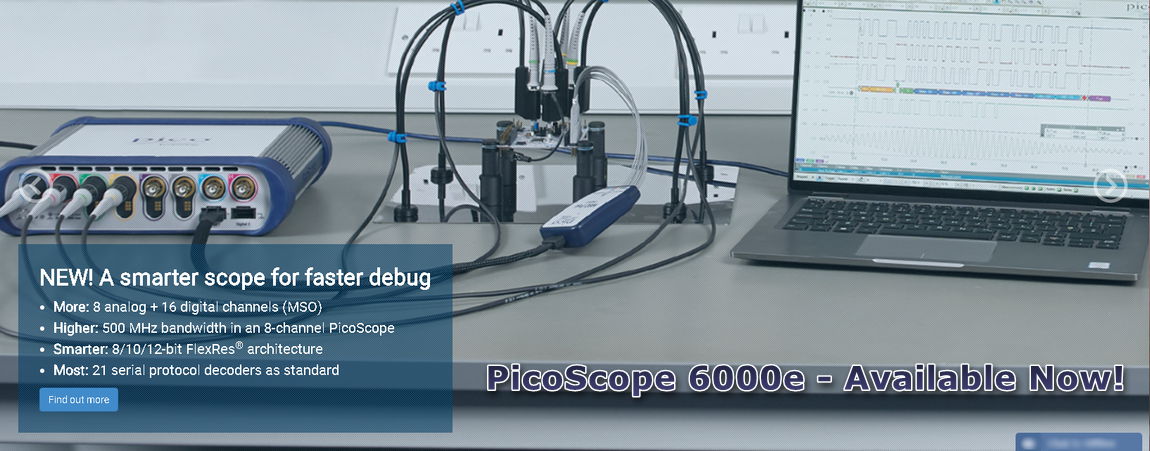
Power, portability and performance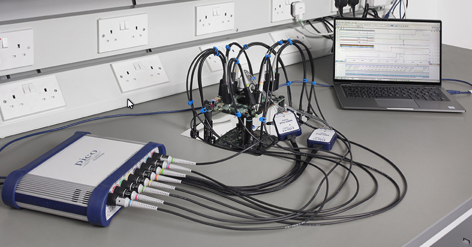
Conventional eight-channel benchtop mixed-signal oscilloscopes occupy too much space on the bench and are too costly for most engineers working on next-generation designs. PicoScope 6000E Series oscilloscopes are small and portable, while offering the high-performance specifications required by engineers in the lab or on the move. High-end features as standard
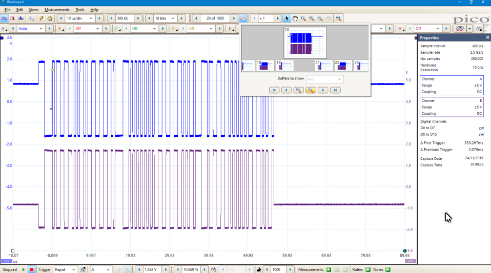
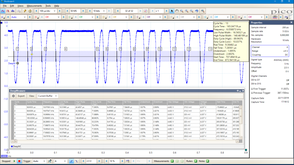
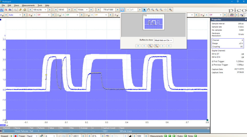
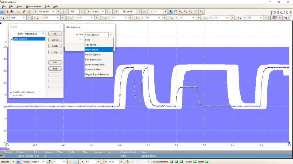
Powerful tools provide endless options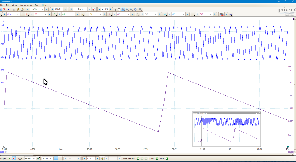 Your PicoScope is provided with many powerful tools to help you acquire and analyze waveforms. While these tools can be used on their own, the real power of PicoScope lies in the way they have been designed to work together. As an example, the rapid trigger mode allows you to collect 10 000 waveforms in a few milliseconds with minimal dead time between them. Manually searching through these waveforms would be time-consuming, so just pick a waveform you are happy with and let the mask tools scan through for you. When done, the measurements will tell you how many have failed and the buffer navigator allows you to hide the good waveforms and just display the problem ones. The screenshot here shows changing frequency versus time as a graph. Perhaps instead you want to plot changing duty cycle as a graph? How about outputting a waveform from the AWG and also automatically saving the waveform to disk when a trigger condition is met? With the power of PicoScope the possibilities are endless. PicoScope 6000E Series with ultra-deep capture memory
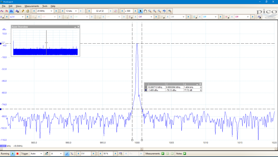
Signal fidelityCareful front-end design and shielding reduce noise, crosstalk and harmonic distortion. PicoScope 6000E Series oscilloscopes exhibit a dynamic performance of up to 60 dB SFDR.
With PicoScope 6, when you probe a circuit, you can trust in the waveform you see on the screen. 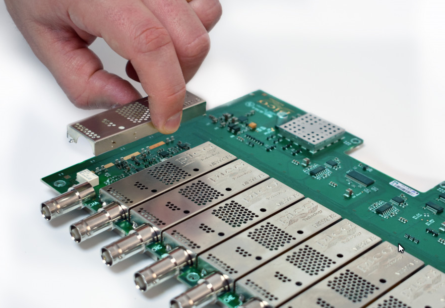 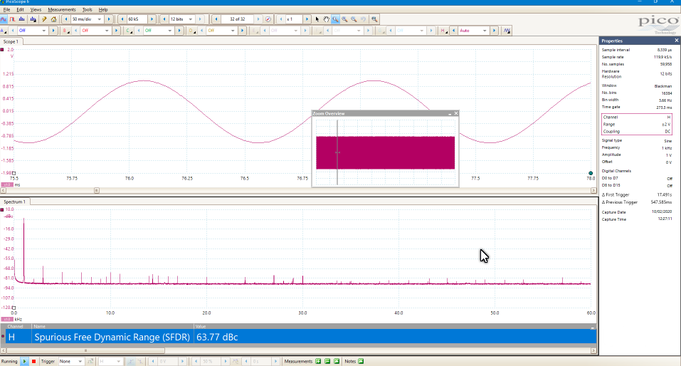 Deep capture memory
With 500 MHz analog bandwidth complemented by a real-time sampling rate of 5 GS/s, the PicoScope 6000E Series scopes can display single-shot pulses with 200 ps time resolution.
The PicoScope 6000E Series gives you the deepest capture memory—up to 4 GS in total—available as standard on any oscilloscope at any price. This ultra-deep memory allows the oscilloscope to capture a 200 ms waveform at its maximum sampling rate of 5 GS/s. The SuperSpeed USB 3.0 interface and hardware acceleration ensure that the display is smooth and responsive even with long captures. The PicoScope 6000E Series gives you the waveform memory, resolution and analysis tools that you need to perform stringent testing of today’s high‑performance embedded computers and next-generation embedded system designs. More information on deep-memory oscilloscopes >> What is FlexRes?
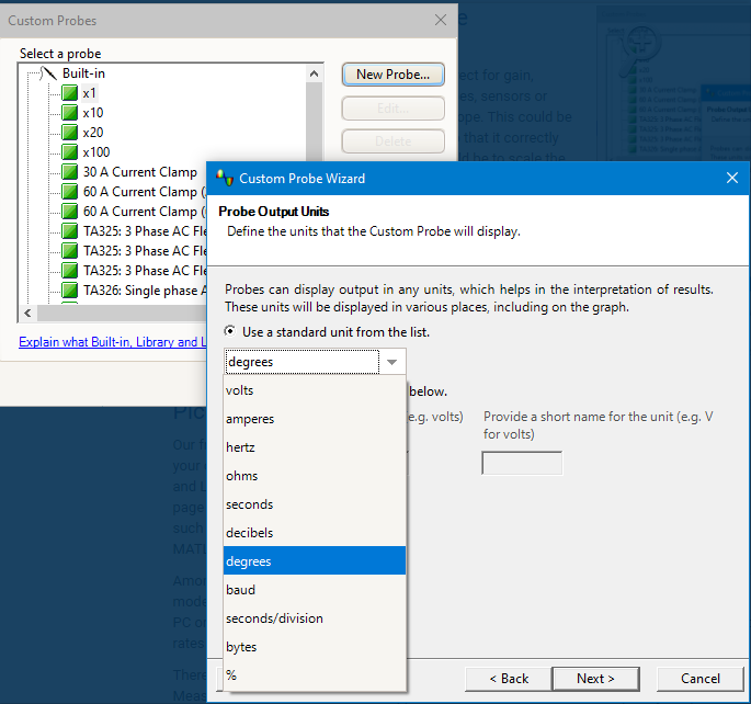
Pico FlexRes flexible-resolution oscilloscopes allow you to reconfigure the scope hardware to optimize either the sampling rate or the resolution.
This means you can reconfigure the hardware to be either a fast (5 GS/s) 8-bit oscilloscope for looking at digital signals or a high-resolution 12-bit oscilloscope for audio work and other analog applications. Whether you’re capturing and decoding fast digital signals or looking for distortion in sensitive analog signals, FlexRes oscilloscopes are the answer. FlexRes is available on the PicoScope 6824E. Resolution enhancement—a digital signal processing technique built into PicoScope 6— can further increase the effective vertical resolution of the scope to 16 bits. More information on flexible resolution >> FlexRes - how we do it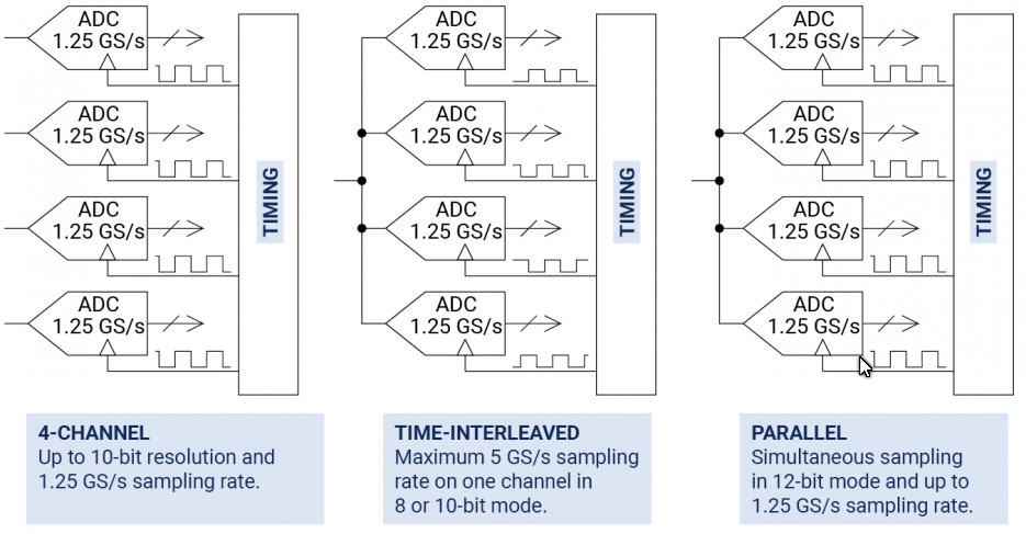
Most digital oscilloscopes gain their high sampling rates by interleaving multiple 8-bit ADCs. This interleaving process introduces errors that always make the dynamic performance worse than that of the individual ADC cores.
The FlexRes architecture employs multiple high-resolution ADCs at the input channels in different time-interleaved and parallel combinations to optimize either the sampling rate to 5 GS/s at 8 bits, the resolution to 12 bits at 1.25 GS/s, or other combinations in between. The diagram shows one bank of four channels; the PicoScope 6824E has two banks. Coupled with high signal-to-noise ratio amplifiers and a low-noise system architecture, FlexRes technology can capture and display signals up to 500 MHz with a high sampling rate, or lower-speed signals with 16 times more resolution than typical 8-bit oscilloscopes. The PicoScope 6 software lets you choose between setting the resolution manually and leaving the scope in auto resolution mode, where the optimal resolution is used for the chosen settings. Mixed-signal options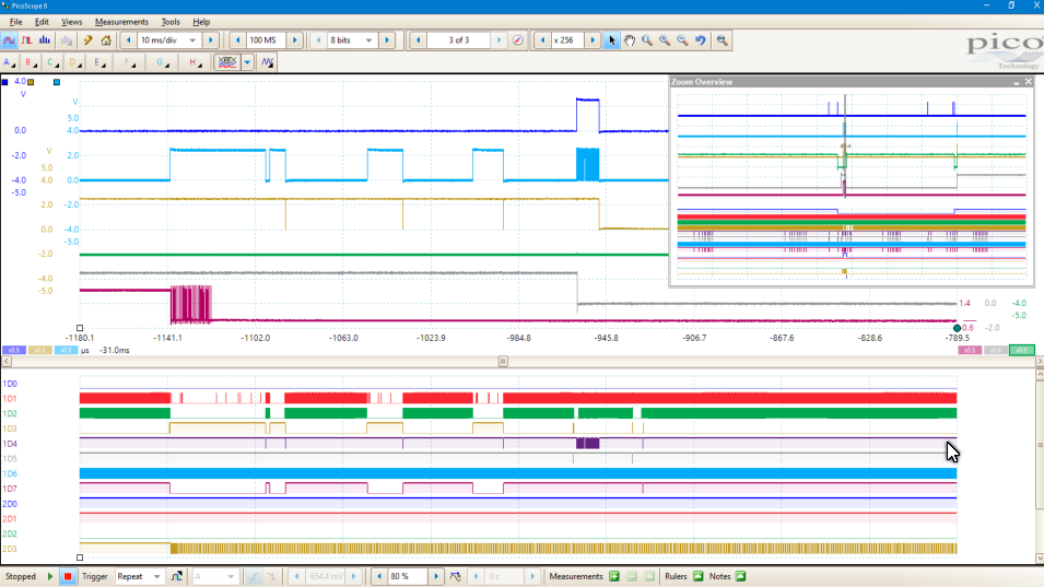
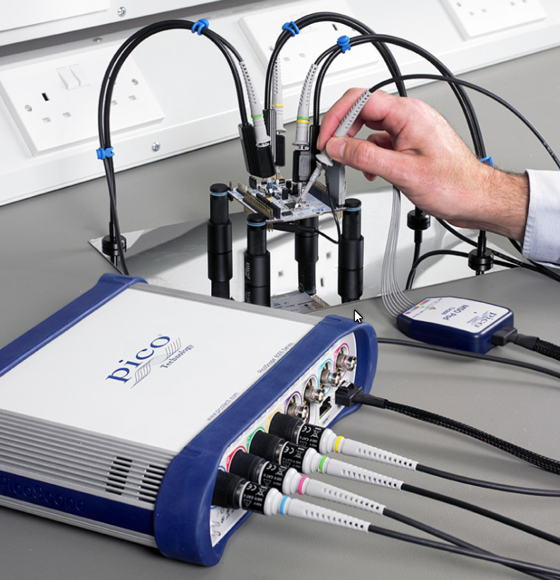
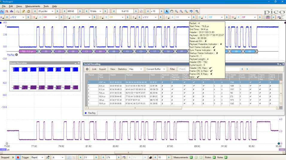
Most benchtop mixed-signal oscilloscopes give you a maximum of four analog channels and 16 digital inputs. When fitted with the optional 8-channel TA369 MSO pods, the PicoScope 6000E Series adds up to 16 high-performance digital channels to its eight analog channels, enabling you to accurately time-correlate analog and digital channels. Digital channel bandwidth is 500 MHz, equivalent to 1 Gb/s, and the input capacitance of only 3.5 pF minimizes loading on the device under test.
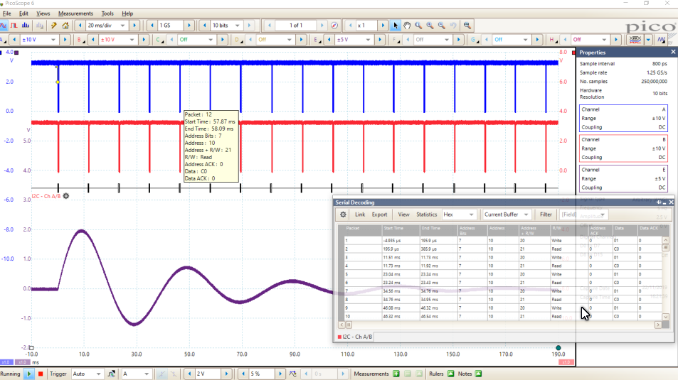
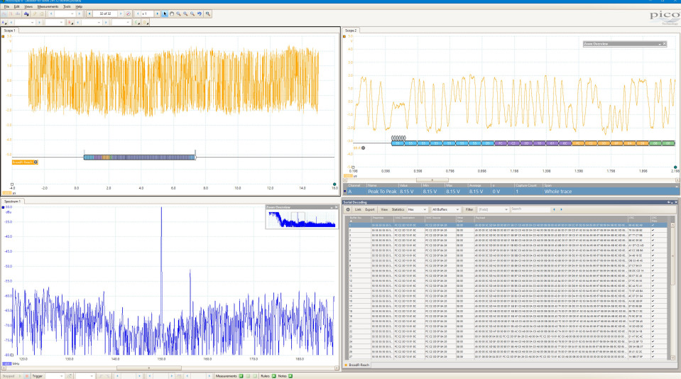
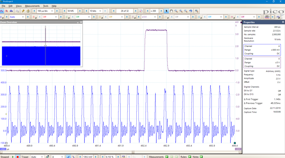
Digital channels, captured from either parallel or multiple serial buses, may be grouped and displayed as a bus, with each bus value displayed in hex, binary or decimal, or as a level (for DAC testing). You can set advanced triggers across the analog and digital channels. The digital inputs also bring extra power to the serial decoding feature. You can decode serial data on all analog and digital channels simultaneously, giving you up to 24 channels of data – for example, decoding multiple SPI, I²C, CAN bus, LIN bus and FlexRay signals all at the same time! More information on mixed-signal oscilloscopes >> High resolution for low-level signals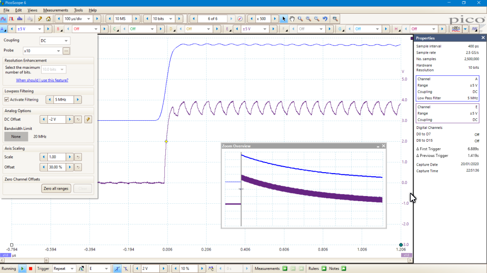 With its 12-bit resolution, the PicoScope 6824E can display low-level signals at high zoom factors. This allows you to view and measure features such as noise and ripple superimposed on larger DC or low-frequency voltages. Additionally, you can use the lowpass filtering controls on each channel independently, to hide noise and reveal the underlying signal. Arbitrary waveform and function generator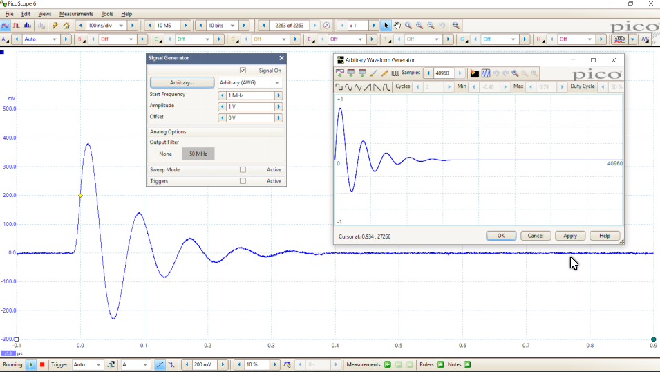 The PicoScope 6000E scopes have a built-in 50 MHz function (sine and square wave) generator, with triangle, DC level, white noise, PRBS and other waveforms possible at lower frequencies. As well as basic controls to set level, offset and frequency, more advanced controls allow you to sweep over a range of frequencies. Combined with the spectrum peakhold option, this makes a powerful tool for testing amplifier and filter responses.
Trigger tools allow one or more cycles of a waveform to be output when various conditions are met, such as the scope triggering or a mask limit test failing. Both models include a 14-bit 200 MS/s arbitrary waveform generator (AWG). This has a variable sample clock, which avoids jitter on waveform edges seen with fixed-clock generators and allows generation of accurate frequencies down to 100 µHz. AWG waveforms can be created or edited using the built-in editor, imported from oscilloscope traces, loaded from a spreadsheet or exported to a .csv file. More information on the arbitrary waveform and function generator >> Digital triggering architecture Many digital oscilloscopes still use an analog trigger architecture based on comparators. This causes time and amplitude errors that cannot always be calibrated out and often limits the trigger sensitivity at high bandwidths.
In 1991 Pico pioneered the use of fully digital triggering using the actual digitized data. This technique reduces trigger errors and allows our oscilloscopes to trigger on the smallest signals, even at the full bandwidth. Trigger levels and hysteresis can be set with high precision and resolution. Advanced triggers The PicoScope 6000E Series offers an industry-leading set of advanced trigger types including pulse width, runt pulse, windowed, logic and dropout. The digital trigger available during MSO operation allows you to trigger the scope when any or all of the 16 digital inputs match a user-defined pattern. You can specify a condition for each channel individually, or set up a pattern for all channels at once using a hexadecimal or binary value. You can also use the logic trigger to combine the digital trigger with an edge or window trigger on any of the analog inputs, for example to trigger on data values in a clocked parallel bus. More information on advanced digital triggers >> Hardware acceleration engine HAL4 Some oscilloscopes struggle when you enable deep memory; the screen update rate slows and the controls become unresponsive. The PicoScope 6000E Series avoids this limitation with the use of a dedicated fourth-generation hardware acceleration (HAL4) engine inside the oscilloscope. Its massively parallel design effectively creates the waveform image to be displayed on the PC screen and allows the continuous capture and display to the screen of 2.5 billion samples every second. The hardware acceleration engine eliminates any concerns about the USB connection or PC processor performance being a bottleneck. TimestampingThe PicoScope 6000E Series features hardware-based trigger timestamping. Each waveform can be time-stamped with the time in sample intervals from the previous waveform. Fast trigger rearm times are possible down to 300 ns (typical). 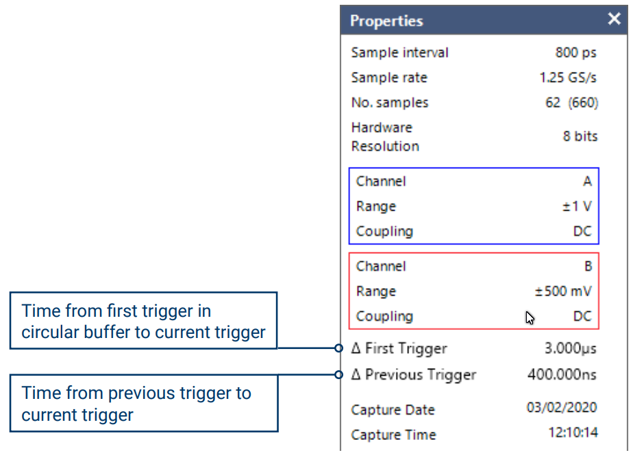 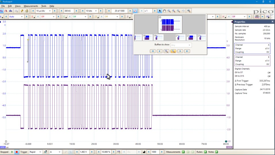 Intelligent probe interface (probes coming soon!)With an intelligent probe interface on channels C to F, the PicoScope 6000E Series will support innovative active probes with a low-profile mechanical design for ease of connectivity and low loading of the device under test. Cost of ownershipTotal cost of ownership (TCO) of a PicoScope 6000E is lower than traditional benchtop instruments for several reasons: 1. Low power consumption - just 60W - saves hundreds of dollars throughout the lifetime of the product compared to benchtop instruments. It's kinder to the environment too, with lower CO2 emissions. 2. Everything's included in the purchase price: serial protocol decoders / math channels/mask limit testing for example. No expensive optional upgrades or annual license fees. 3. Free updates. New features and capabilities are provided throughout the lifetime of the product as we develop and release them. 
PicoScope 6000E Series software
|
|||||||||||||||||||||||||||||||||||||||||||||||||||||||||||||||||||||||||||||||||||||||||||||||||||||||||||||||||||||||||||||||||||||||||||||||||||||||||||||||||||||||||||||||||||||||||||||||||||||||||||||||||||||||||||||||||||||||||||||||||||||||||||||||||||||||||||||||||||||||||||||||||||||||||||||||||||||||||||||||||||||||||||||||||||||||||||||||||||||||||||||||||||||||||||||||||||||||||||||||||||||||||||||||||||||||||||||||||||||||||||||||||||||||||||||||||||||||||||||||||||||||||||||||||||||||||||||||||||||||||||||||||||||||||||||||||||||||||||||||||||||||||||||||||||||||||||||||||||||||||||||||||||||||||||||||||||||||||||||||||||||||||||||||||||||||||||||||||||||||||||||||||||||||||||||||||||||||||||||||||||||||||||||||||||||||||||||||||||||||||||||||||||||||||||||||||||||||||||||||||||||||||||||||||||||||||||||||||||||||||||||||||||||||||||||||||||||||||||||||||||||||||||||||||||||||||||||||||||||||||||||||||||||||||||||||||||||||||||||||||||||||||||||||||||||||||||||||||||||||


| Resource | Language | Version | Size | Updated |
| Data Sheet: | ||||
| PicoScope 6000E Series Data Sheet | English | 4 | 20 MB | May 22, 2020 |
| User’s Guides: | ||||
| TA369 8-channel MSO Pod User’s Guide | English | 1 | 2 MB | February 7 2020 |
| PicoScope 6 User’s Guide | English | 50 | 10 MB | February 24 2020 |
| Quick Start Guides: | ||||
| PicoScope 6000E Series Quick Start Guide | English Français Deutsch Italiano Español ä¸æ–‡ (简体) í•œêµì–´ 日本èª� |
1 | 8 MB | February 13 2020 |
| Declarations: | ||||
| PicoScope 6000E EU Declaration of Conformity | English | 1 | 2 MB | February 19 2020 |
| Magazine or Web Site Reviews | ||||
| Element14 Review of the Picoscope 6424E | ||||
Accessories
Our ergonomically designed passive oscilloscope probes are suitable for use with all major brands of oscilloscopes as well as the PicoScope range of USB Oscilloscopes. Passive probes don't require a power supply or batteries so are lightweight and easily portable.
Read our free guide: How to Tune x10 Oscilloscope Probes.
| Standard Passive Probes | ||
| Product | Description | Order |
 |
P2056 passive oscilloscope probe: 500 MHz 2.5 mm 10:1, BNC, dual pack TA480 Recommended |
|
|
|
P2056 passive oscilloscope probe: 500 MHz 2.5 mm 10:1, BNC, single pack TA437 Recommended |
|
| Passive Probe Accessories | ||
 |
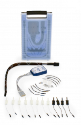
8-channel probe holder kit for PicoScope 6000E Series PQ219 Recommended |
|
 |
Probe holder kit, no probes PQ215 Recommended |
|
 |
2.5 mm oscilloscope probe advanced accessory kit TA065 |
|
 |
2.5 mm oscilloscope probe basic accessory kit TA066 |
|
 |
2.5 mm oscilloscope probe solid contact tips, pack of 5 TA068 |
|
 |
2.5 mm oscilloscope probe spring contact tips, pack of 5 TA064 |
|
 |
2.5 mm oscilloscope probe standard accessory kit TA067 |
|
 |
Probe tip to BNC adaptor TA152 |
|
| Miscellaneous | ||
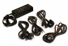 |
PS016 12 V power adaptor with IEC leads PQ247 |
|
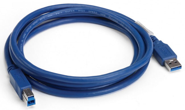 |
USB 3.0 cable, 1.8 m TA155 |
|
 |
PicoScope 6000E Series MSO pod, 8 channels TA369 Recommended |
|
| A3000 Active Probes | ||

PicoScope 6000E Series specifications
| Model | PicoScope | |||
|---|---|---|---|---|
| Bandwidth (–3 dB) | 300 MHz | 500 MHz | 750 MHz | 1 GHz |
| 4- channel 8-bit | 6403E | 6404E | 6405E | 6406E |
| 4-channel FlexRes | 6424E | 6425E | 6426E | |
| 8-channel 8-bit | 6804E | |||
| 8-channel FlexRes | 6824E | |||
| Vertical (analog channels) | ||||
|---|---|---|---|---|
| Bandwidth (–3 dB) | 300 MHz | 500 MHz | 50 Ω ranges: 750 MHz 1 MΩ ranges: 500 MHz |
50 Ω ranges: 1 GHz 1 MΩ ranges: 500 MHz |
| Rise time | < 1.3 ns | < 850 ps | 50 Ω ranges: < 475 ps 1 MΩ ranges: < 850 ps |
50 Ω ranges: < 350 ps 1 MΩ ranges: < 850 ps |
| Bandwidth limiter | 20 MHz. Software-switchable. | 20 MHz or 200 MHz. Software-switchable. | ||
| Vertical resolution[2] | FlexRes models: 8, 10 or 12 bits Other models: 8 bits |
|||
| LSB size[2] (quantization step size) | 8-bit mode: < 0.4% of input range 10-bit mode (FlexRes models): < 0.1% of input range 12-bit mode (FlexRes models): < 0.025% of input range |
|||
| Enhanced vertical resolution | Hardware resolution up to 4 bits | |||
| Input connector | BNC(f). x10 readout-pin compatible. Intelligent Probe Interface on all channels (4-channel models) or on channels C to F (8-channel models). | |||
| Input ranges | 1 MΩ ranges: ±10 mV, ±20 mV, ±50 mV, ±100 mV, ±200 mV, ±500 mV, ±1 V, ±2 V, ±5 V, ±10 V, ±20 V 50 Ω ranges: ±10 mV to ±5 V as above |
|||
| Input sensitivity | 1 MΩ ranges: 2 mV/div to 4 V/div (10 vertical divisions) 50 Ω ranges: 2 mV/div to 1 V/div (10 vertical divisions) |
|||
| Input coupling | 1 MΩ ranges: AC / DC 50 Ω ranges: DC |
|||
| Input characteristics | 1 MΩ ±0.5% ∥ 12 pF ±1 pF | |||
| 50 Ω ±2% | 50 Ω ±3% | |||
| DC gain accuracy (8-bit models) | ±(1.5% of signal 1 LSB) | ±(1.5% of signal 1 LSB) | ±(1.5% of signal 1 LSB) | |
| DC gain accuracy (FlexRes models) | N/A | ±(0.5% of signal 1 LSB) | ±(1% of signal 1 LSB) | |
| DC offset accuracy | ±(1% of full scale 250 μV). Can be improved by using the “zero offset” function in PicoScope 6. |
|||
| Analog offset range (vertical position adjust) | 50 Ω ranges: ±1.25 V (±10 mV to ±1 V ranges) ±20 V (±2 V to ±20 V ranges) |
50 Ω ranges: ±125 mV (±10 mV to ±100 mV ranges) ±1.25 V (±200 mV to ±1 V ranges) ±5 V (±2 V and ±5 V ranges) |
||
| 1 MΩ ranges: ±1.25 V (±10 mV to ±1 V ranges) ±20 V (±2 V to ±20 V ranges) |
||||
| Analog offset control accuracy | ±0.5% of offset setting, additional to basic DC offset accuracy | |||
| Overvoltage protection | 1 MΩ ranges: ±100 V (DC AC peak) up to 10 kHz 50 Ω ranges: 5.5 V RMS max, ± 10V pk max |
|||
| Vertical (digital channels, with optional TA369 8-channel MSO pods) | ||||
|---|---|---|---|---|
| Input channels | 16 channels (2 ports of 8 channels each) | |||
| Maximum detectable input frequency | 500 MHz (1 Gb/s) | |||
| Minimum detectable pulse width | 1 ns | |||
| Input connector (probe tip) | Staggered signal and ground sockets for each channel, to accept 0.64 – 0.89 mm round or 0.64 mm square pin, 2.54 mm pitch | |||
| Input characteristics | 101 kΩ ±1% ∥ 3.5 pF ±0.5 pF | |||
| Maximum input voltage at probe tip | ±40 V up to 10 MHz, derated linearly to ±5 V at 500 MHz | |||
| Threshold range and resolution | ±8 V in approx. 5 mV steps | |||
| Threshold grouping | PicoScope 6: Two independent threshold controls, one per 8-channel port PicoSDK: Individual threshold for each channel |
|||
| Threshold selection | TTL, CMOS, ECL, PECL, user-defined | |||
| Threshold accuracy | ±(100 mV 3% of threshold setting) | |||
| Minimum input voltage swing (at maximum frequency) | 400 mV peak to peak | |||
| Hysteresis (at DC) | PicoScope 6: Fixed hysteresis approx. 100 mV PicoSDK: selectable per port; approx. 50 mV, 100 mV, 200 mV or 400 mV |
|||
| Minimum input slew rate | No minimum slew rate requirement | |||
| Horizontal | ||||
|---|---|---|---|---|
| Maximum sampling rate (real-time, 8-bit) | ||||
| Up to 2 channels[4], 0 or 1 analog | 5 GS/s | 4-ch models: 5 GS/s[1] 8-ch models: 5 GS/s[3] |
5 GS/s[1] | |
| Up to 4 channels, 2 analog | 2.5 GS/s[1] | 4-ch models: 2.5 GS/s 8-ch models: 2.5 GS/s[2] |
2.5 GS/s | |
| Up to 4 channels, 3 or 4 analog | 1.25 GS/s | |||
| Up to 8 channels | 1.25 GS/s | |||
| More than 8 channels | N/A | 625 MS/s | N/A | |
| Maximum sampling rate (real time, 10-bit, FlexRes models only) | ||||
| 1 channel | N/A | 5 GS/s | ||
| Up to 2 channels | 6824E: 2.5 GS/s[2] 6424E: 2.5 GS/s |
2.5 GS/s | ||
| Up to 4 channels | 1.25 GS/s | |||
| Up to 8 channels | 625 MS/s | |||
| More than 8 channels | 6424E: N/A 6824E: 312.5 MS/s |
N/A | ||
| Maximum sampling rate (real time, 12-bit, up to 2 channels, FlexRes models only) | ||||
| 1 to 2 analog channels plus 0 to 2 digital ports | N/A | 6824E: 1.25 GS/s[3] 6424E: 1.25 GS/s[1] |
1.25 GS/s[1] | |
| [1] No more than one channel from each of AB and CD. [2] No more than one channel from each of AB, CD, EF and GH. [3] No more than one channel from each of ABCD and EFGH. [4] In this section a channel counts as either an analog input or an 8-bit MSO port. |
||||
| Max. sampling rate, USB 3.0 streaming mode (split between active channels, PC dependent) | ||||
| PicoScope 6 | ~20 MS/s | |||
| PicoSDK | ~312 MS/s | ~312 MS/s (8-bit mode) ~156 MS/s (10/12-bit modes, FlexRes models) |
||
| Max. sampling rate to on-device buffer (continuous USB streaming of raw or downsampled data, split between enabled channels) | ||||
| PicoSDK only | 1.25 GS/s | 1.25 GS/s (8-bit mode) 625 MS/s (10/12-bit modes, FlexRes models) |
||
| Capture memory (shared between active channels) | ||||
| 8-bit models | 1 GS | 2 GS | ||
| FlexRes models, 8-bit mode | N/A | 4 GS | ||
| FlexRes models, 10- and 12-bit modes | 2 GS | |||
| Maximum single capture duration at maximum sampling rate | ||||
| PicoScope 6 | 200 ms | |||
| 8-bit models, PicoSDK | 200 ms | 400 ms | ||
| 8-bit, PicoSDK, FlexRes models | N/A | 800 ms | ||
| 10-bit, PicoSDK, FlexRes models | N/A | 400 ms | ||
| 12-bit, PicoSDK, FlexRes models | 1600 ms | |||
| Capture memory (continuous streaming) | 100 MS in PicoScope software. Buffering using full device memory when using PicoSDK, no limit on total duration of capture. | |||
| Waveform buffer (number of segments, PicoScope 6) | 10 000 | |||
| Waveform buffer (number of segments, PicoSDK) | 1 000 000 | 2 000 000 | ||
| Timebase ranges | 1 ns/div to 5000 s/div | |||
| Initial timebase accuracy | ±2 ppm | |||
| Timebase drift | ±1 ppm/year | |||
| ADC sampling | Simultaneous sampling on all enabled analog and digital channels | |||
| External reference clock | ||||||
|---|---|---|---|---|---|---|
| Input characteristics | Hi-Z, AC coupled (> 1 kΩ at 10 MHz) | |||||
| Input frequency range | 10 MHz ±50 ppm | |||||
| Input connector | Rear-panel BNC(f), dedicated | |||||
| Input level | 200 mV to 3.3 V peak to peak | |||||
| Overvoltage protection | ±5 V peak max | |||||
| Dynamic performance (typical; analog channels) | ||||
|---|---|---|---|---|
| 300 MHz | 500 MHz | 750 MHz | 1 GHz | |
| Crosstalk | 1200:1 (±10 mV to ±1 V ranges) 300:1 (±2 V to ±20 V ranges) |
2500:1 (±10 mV to ±1 V ranges) 600:1 (±2 V to ±20 V ranges) |
||
| from DC to bandwidth of victim channel, equal voltage ranges | ||||
| Harmonic distortion, 8-bit mode | –50 dB at 1 MHz full scale | |||
| Harmonic distortion, 10/12-bit mode, FlexRes models | –60 dB at 1 MHz full scale, typical | |||
| SFDR, 8-bit models | > 50 dB on ±50 mV to ±20 V ranges | |||
| SFDR, FlexRes models | > 60 dB on ±50 mV to ±20 V ranges | |||
| Noise, 8-bit models | < 200 μV RMS on most sensitive range | |||
| Noise, FlexRes models | < 150 μV RMS on most sensitive range | |||
| Bandwidth flatness | ( 0.3 dB, –3 dB) from DC to full bandwidth | |||
| Low frequency flatness | < ±3% (or ±0.3 dB) from DC to 1 MHz | |||
| Triggering (main specifications) | ||||||
|---|---|---|---|---|---|---|
| Source | Any analog channel, AUX trigger, plus digital ports with optional TA369 MSO pods | |||||
| Trigger modes | None, auto, repeat, single, rapid (segmented memory) | |||||
| Advanced trigger types (analog channels) | Edge, window, pulse width, window pulse width, level dropout, window dropout, interval, runt, logic. Logic allows arbitrary combinations of up to 4 analog channels or MSO ports. |
|||||
| Trigger sensitivity (analog channels) | Digital triggering provides 1 LSB accuracy up to full bandwidth of scope. | |||||
| Trigger types (digital inputs) | With optional MSO pods: Edge, pulse width, dropout, interval, logic, pattern, mixed signal | |||||
| Pre-trigger capture | Up to 100% of capture size | |||||
| Post-trigger delay and other time intervals | PicoScope 6: 0 to > 4 x 10⁹ samples, settable in 1 sample steps (delay range at fastest sample rate of 0.8 s in 200 ps steps) PicoSDK: 0 to > 1012 samples, settable in 1 sample steps (delay range at fastest sample rate of > 200 s in 200 ps steps) |
|||||
| Rapid trigger mode rearm time | 700 ns max, 300 ns typical (single channel, 5 GS/s) | |||||
| Maximum trigger rate | PicoScope 6: 10 000 waveforms in 3 ms; PicoSDK: 6 million waveforms per second | |||||
| Trigger time-stamping | Each waveform is timestamped in sample intervals (PicoSDK) or time (PicoScope 6) from previous waveform. The time resets when any settings are changed. |
|||||
| Auxiliary trigger input | ||||||
|---|---|---|---|---|---|---|
| Connector type | Rear-panel BNC(f) | |||||
| Trigger types (triggering scope) | Edge, pulse width, dropout, interval, logic | |||||
| Input characteristics | 2.5 V CMOS high-impedance input, DC coupled | |||||
| Bandwidth | > 10 MHz | |||||
| Threshold range | Fixed threshold, 1.25 V nominal to suit 2.5 V CMOS | |||||
| Hysteresis | 1 V max (VIH < 1.75V, VIL > 0.75V) | |||||
| Overvoltage protection | ±20 V peak max | |||||
| Function generator | ||||||
|---|---|---|---|---|---|---|
| Standard output signals | Sine, square, triangle, DC voltage, ramp up, ramp down, sinc, Gaussian, half-sine | |||||
| Pseudorandom output signals | White noise, selectable amplitude and offset within output voltage range. Pseudorandom binary sequence (PRBS), selectable high and low levels within output voltage range, selectable bit rate up to 50 Mb/s |
|||||
| Standard signal frequency | Sine (filtered): 100 μHz to 50 MHz; Square (full bandwidth): 100 μHz to 50 MHz; Other waves: 100 μHz to 1 MHz | |||||
| Sweep modes | Up, down, dual with selectable start / stop frequencies and increments | |||||
| Sweep frequency range | Sine / square waves: 0.075 Hz to 50 MHz Other waves: 0.075 Hz to 1 MHz Swept frequencies down to 100 μHz possible in PicoSDK with some restrictions |
|||||
| Sweep frequency resolution | In PicoScope 6 software: 0.075 Hz Sweep frequency resolution down to 100 μHz possible in PicoSDK with some restrictions. |
|||||
| Triggering | Free-run, or from 1 to 1 billion counted waveform cycles or frequency sweeps. Triggered from scope trigger or manually. | |||||
| Gating | Software controlled gating of waveform output | |||||
| Output frequency accuracy | Oscilloscope timebase accuracy ± output frequency resolution | |||||
| Output frequency resolution | 0.002 ppm | |||||
| Output voltage range | ±5 V into open circuit; ±2.5 V into 50 Ω | |||||
| Output voltage adjustment | Signal amplitude and offset adjustable in < 1 mV steps within overall range | |||||
| Amplitude flatness | < 2.0 dB to 50 MHz (sine wave into 50 Ω) < 0.5 dB to 50 MHz (square) < 1.0 dB to 1 MHz (other waveforms) |
|||||
| Analog filters | 50 MHz selectable filter (5-pole, 30 dB/octave) | |||||
| DC accuracy | ±(0.5% of output voltage 20 mV) | |||||
| SFDR | 70 dB (10 kHz 1 V peak to peak sine into 50 Ω) | |||||
| Output noise | < 700 μV RMS (DC output, filter enabled, into 50 Ω) | |||||
| Output resistance | 50 Ω ±3% | |||||
| Connector type | Rear-panel BNC(f) | |||||
| Overvoltage protection | ±20 V peak max | |||||
| Arbitrary waveform generator | ||||||
|---|---|---|---|---|---|---|
| Update rate | Variable from < 1 S/s to 200 MS/s with < 0.002 ppm resolution | |||||
| Buffer size | 40 kS | |||||
| Resolution | 14 bits (output step size < 1 mV) | |||||
| Bandwidth (−3 dB) | No filter: 100 MHz Filtered: 50 MHz |
|||||
| Rise time (10% to 90%) | No filter: 3.5 ns Filtered: 6 ns |
|||||
Additional AWG specifications including sweep modes, triggering, frequency accuracy and resolution, voltage range, DC accuracy and output characteristics are as the function generator
| Probe support | ||||
|---|---|---|---|---|
| Intelligent probe interface | Intelligent probe interface on four channels supporting A3000 Series active probes. Probe interface supplies power and controls the probe. | |||
| Probe detection | Automatic detection of Pico P2036, P2056 x10 passive oscilloscope probes, and A3000 Series active probes. | |||
| Probe compensation pin | 1 kHz, 2 V peak to peak square wave, 600 Ω | |||
| Probe compensation pin rise time | < 50 ns | |||
| Spectrum analyzer | ||||||
|---|---|---|---|---|---|---|
| Frequency range | DC to oscilloscope's rated bandwidth | |||||
| Display modes | Magnitude, average, peak hold | |||||
| Y axis | Logarithmic (dbV, dBu, dBm, arbitrary dB) or linear (volts) | |||||
| X axis | Linear or logarithmic | |||||
| Windowing functions | Rectangular, Gaussian, triangular, Blackman, Blackman–Harris, Hamming, Hann, flat-top | |||||
| Number of FFT points | Selectable from 128 to 1 million in powers of 2 | |||||
| Math channels | ||||||
|---|---|---|---|---|---|---|
| Functions | −x, x y, x−y, x*y, x/y, x^y, sqrt, exp, ln, log, abs, norm, sign, sin, cos, tan, arcsin, arccos, arctan, sinh, cosh, tanh, delay, average, frequency, derivative, integral, min, max, peak, duty, highpass, lowpass, bandpass, bandstop | |||||
| Operands | A, B, C, D (input channels), T (time), reference waveforms, pi, 1D0−2D7 (digital channels), constants | |||||
| Automatic measurements | ||||||
|---|---|---|---|---|---|---|
| Scope mode | AC RMS, true RMS, frequency, cycle time, duty cycle, DC average, falling rate, rising rate, low pulse width, high pulse width, fall time, rise time, minimum, maximum, peak to peak | |||||
| Spectrum mode | Frequency at peak, amplitude at peak, average amplitude at peak, total power, THD %, THD dB, THD N, SFDR, SINAD, SNR, IMD | |||||
| Statistics | Minimum, maximum, average, standard deviation | |||||
| DeepMeasure™ | ||||||
|---|---|---|---|---|---|---|
| Parameters | Cycle number, cycle time, frequency, low pulse width, high pulse width, duty cycle (high), duty cycle (low), rise time, fall time, undershoot, overshoot, max. voltage, min. voltage, voltage peak to peak, start time, end time | |||||
| Serial decoding | ||||||
|---|---|---|---|---|---|---|
| Protocols | 1-Wire, ARINC 429, CAN, CAN FD, DALI, DCC, DMX512, Ethernet 10Base-T and 100Base-TX, FlexRay, I²C, I²S, LIN, Manchester, MODBUS, PS/2, MODBUS, SENT, SPI, UART (RS-232), USB 1.1 | |||||
| Mask limit testing | ||||
|---|---|---|---|---|
| Statistics | Pass/fail, failure count, total count | |||
| Mask creation | User-drawn, table entry, auto-generated from waveform or imported from file | |||
| Display | ||||
|---|---|---|---|---|
| Interpolation | Linear or sin(x)/x | |||
| Persistence modes | Digital color, analog intensity, custom, fast | |||
| Output functions | Copy to clipboard, print | |||
| Output file formats | BMP, CSV, GIF (static and animated), JPG, MAT, PDF, PNG, PSDATA, PSSETTINGS, TXT | |||
| Software | ||||
|---|---|---|---|---|
| Windows software (32-bit or 64-bit)[5] |
PicoScope 6, PicoLog 6, PicoSDK (Users writing their own apps can find example programs for all platforms on the Pico Technology organization page on GitHub) | |||
| macOS software (64-bit)[5] | PicoScope 6 Beta (including drivers), PicoLog 6 (including drivers) | |||
| Linux software (64-bit)[5] | PicoScope 6 Beta software and drivers, PicoLog 6 (including drivers) See Linux Software and Drivers to install drivers only |
|||
| Raspberry Pi 4B (Raspberry Pi OS)[5] |
PicoLog 6 (including drivers) See Linux Software and Drivers to install drivers only |
|||
| [5] See www.picotech.com/downloads for more information. | ||||
| Languages supported, PicoScope 6 | Chinese (simplified), Chinese (traditional), Czech, Danish, Dutch, English, Finnish, French, German, Greek, Hungarian, Italian, Japanese, Korean, Norwegian, Polish, Portuguese, Romanian, Russian, Spanish, Swedish, Turkish | |||
| Languages supported, PicoLog 6 | Simplified Chinese, Dutch, English (UK), English (US), French, German, Italian, Japanese, Korean, Russian, Spanish | |||
| PC requirements | Processor, memory and disk space: as required by the operating system Ports: USB 3.0 (recommended) or 2.0 (compatible) |
|||
| General | ||||
|---|---|---|---|---|
| Package contents |
|
|||
| PC connectivity | USB 3.0 SuperSpeed (USB 2.0 compatible) | |||
| USB connector | Type B | |||
| Power requirements | 12 V DC from supplied PSU. Up to 5 A (scope only) or 7 A including scope-powered accessories | |||
| Ground terminal | Functional ground terminal accepting wire or 4 mm plug, rear-panel | |||
| Thermal management | Automatic fan speed control for low noise | |||
| Dimensions | 245 x 192 x 61.5 mm | |||
| Weight | 2.2 kg (scope only) 5.6 kg (in carry case with PSU and cables) |
|||
| Temperature range | Operating: 0 to 40 °C 15 to 30 °C for quoted accuracy after 1 hour warm-up Storage: –20 to 60 °C |
|||
| Humidity range | Operating: 5 to 80 %RH non-condensing Storage: 5 to 95 %RH non-condensing |
|||
| Altitude range | Up to 2000 m | |||
| Pollution degree | EN 61010 pollution degree 2 | |||
| Safety compliance | Designed to EN 61010-1:2010 A1:2019 | |||
| EMC compliance | Tested to EN61326-1:2013 and FCC Part 15 Subpart B | |||
| Environmental compliance | RoHS, REACH, WEEE | |||
| Warranty | 5 years | |||
Order your 6000e Series Scope online today!
Pico Have Changed all 6000 series SKU Numbers - We are currently transitioning our web site to reflect these changes
If you cannot find the price for a model of interest, please call or email us.
| None of the models here include Pods, however, some do include probes and some models are without probes. 4 Channel units with probes, have 4 probes and 8 Channel units, have 8 Probes. |
| PQ301 Picoscope 6406E-D4 - 4 Ch, 1 Ghz B/W, 8 bits, 2GS Memory With 4 Oscilloscope Probes *** NEW PRODUCT*** [no pods or active probes] [old # was PQ309] |
PQ303 Picoscope 6426E-D4 - 4 Ch, 1 Ghz B/W, 8/10/12 bits [FLEXRES], 2GS Memory ‹With 4 Oscilloscope Probes *** NEW PRODUCT*** [no pods or active probes] [old # was PQ311] |
| PQ305 Picoscope 6406E-D4 - 4 Ch, 1 Ghz B/W, 8 bits, 2GS Memory Without 4 Oscilloscope Probes *** NEW PRODUCT*** [no pods or active probes] [old # was PQ313] |
PQ344 Picoscope 6428E-D - 4 Channel 3 GHz B/W, FlexRes 8/10/12 bit Resolution. Probes and MSO Pods available but optional. |
| PQ306 PicoScope 6425E 750 MHz, 4 channel, FLEXRES kit *** NEW PRODUCT*** [old # was PQ314] |
PQ307 Picoscope 6426E-D4 - 4 Ch, 1 Ghz B/W, 8/10/12 bits [FLEXRES], 2GS Memory ‹Without Oscilloscope Probes *** NEW PRODUCT*** [no pods or active probes] [old # was PQ315] |
| PQ302 PicoScope 6425E 750 MHz, 4 channel, FLEXRES kit *** NEW PRODUCT*** [old # was PQ310] |
PQ300 PicoScope 6405E 750 MHz, 4 channel, 8-bit kit US PSU, with probes *** NEW PRODUCT*** [old # was PQ308] |
| PQ304 PicoScope 6405E 750 MHz, 4 channel, 8-bit kit US PSU, without probes*** NEW PRODUCT*** [old # was PQ312] |
|
| PQ197 Picoscope 6804E - 8 Ch, 500 Mhz With Probes [old # was PQ204] |
PQ198 Picoscope 6824E - 8 Ch, 500MHz, FLEXRES With Probes [old # was PQ205] |
| PQ241 Picoscope 6804E - 8 Ch, 500 Mhz W/O Probes [old # was PQ248] |
PQ242 Picoscope 6824E - 8 Ch, 500MHz, FLEXRES W/O Probes [old # was PQ249] |
| PQ199 Picoscope 6403E - 4 Ch, 300MHz, With Probes [old # was PQ206] |
PQ200 Picoscope 6404E - 4Ch, 500MHz, With Probes [old # was PQ207] |
| PQ243 Picoscope 6403E - 4 Ch, 300MHz, W/O Probes [old # was PQ250] |
PQ244 Picoscope 6404E - 4Ch, 500MHz, W/O Probes [old # was PQ251] |
| PQ201 Picoscope 6424E - 4 Channel With 2 Probes - 0 Pods [old # was PQ208] |
| PQ245 Picoscope 6424E-D4 - 4 Channel (No Probes or Pods) [old # was PQ252] |
| Probes and PODS | |
| TA479 - P2036 Passive Oscilloscope Probe 300 Mhz, 2.5mm, 10:1, BNC, Dual Pack |
TA480 - P2056 Passive Oscilloscope Probe 500 Mhz, 2.5mm, 10:1, BNC, Dual Pack |
| TA369 - Picoscope 6000e Series MSO Pod. 8 Channel | |
Download Product Data Sheet Here - 19.6Mb