


|
|
|||
 |
|||
| Log In | |||
|
|||
|
|||
|
| |||
|
|||
| |||
|
|||
| |||



Crystal-clear waveform analysis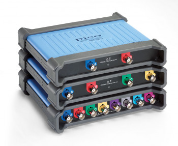 The PicoScope 4000A Series of PC oscilloscopes is a second-generation upgrade and expansion of our high-resolution, deep-memory product portfolio. With 2-, 4- and 8-channel models available, the PicoScope 4000A Series boasts 12-bit hardware resolution (to 16 bits with Resolution Enhancement), 256 MS deep capture memory, 20 MHz bandwidth with 80 MS/s sampling speed, up to 70 dB SFDR and a built-in 14-bit triggerable signal generator and 80 MS/s AWG. A SuperSpeed USB 3.0 interface powers the instrument and delivers up to 160 MS/s communications to the host PC. All models run with the popular PicoScope 6 user interface and benefit from the free PicoSDK software development kit, which gives users direct programming control of the hardware for custom applications. The scopes also work with PicoLog 6 data logging software for lower-speed long-duration captures. The following features come as standard on all 4000A oscilloscopes: 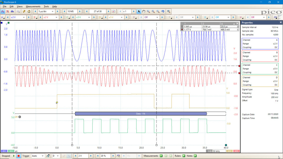
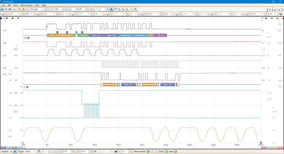
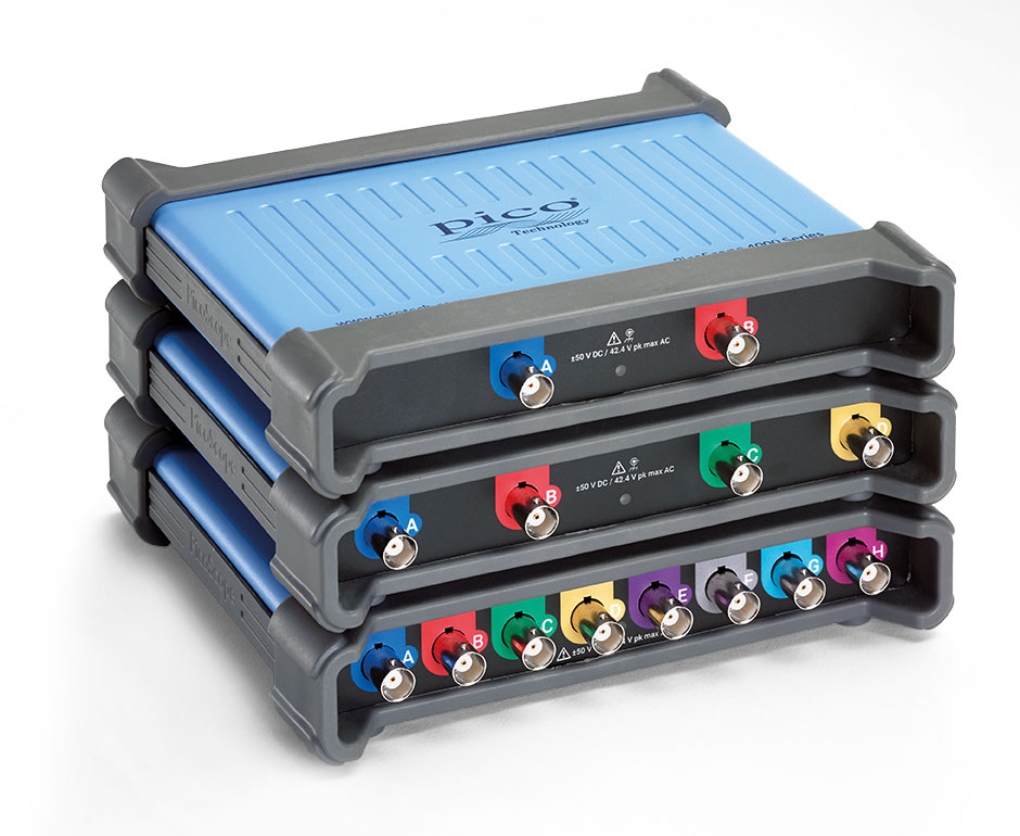
Up to 8 channels of high resolutionWith the PicoScope 4000A Series providing a choice of either 2, 4 or 8 high-resolution analog channels you can easily view audio, ultrasonic, vibration and power waveforms, analyze timing of complex systems, and perform a wide range of precision measurement tasks on multiple inputs at the same time. The scopes have a small, compact footprint, yet the BNC connectors with a minimum 20 mm spacing still accept all common probes and accessories. Despite their compact size, there is no compromise on performance. With a high vertical resolution of 12 bits, 20 MHz bandwidth, 256 MS buffer memory, and a fast sampling rate of 80 MS/s, the PicoScope 4000A Series has the power and functionality to deliver accurate results. With up to 8 channels, these oscilloscopes can analyze multiple serial buses such as UART, I2C, SPI, Why choose the PicoScope 4000A Series oscilloscopes?The PicoScope 4000A Series provides 20 MHz bandwidth, low noise, 12-bit resolution, deep capture memory The PicoScope 4000A Series is unlike conventional oscilloscopes with 8-bit resolution and limited capture
  Suitable for a broad range of applications, including:
Complex embedded systemsWhen debugging an embedded system with a scope, you can quickly run out of channels. You may need to look at an I2C or SPI bus at the same time as multiple power rails, DAC outputs and logic signals. With up to eight channels, the PicoScope 4000A Series can cope with all of this. Choose whether to decode up to eight serial buses, with analog waveforms and decoded data both visible, or a combination of serial buses and other analog or digital signals. PicoScope provides advanced triggering on all channels, so you can search for runt pulses, dropouts and noise as well as looking for data patterns using the 4-input Boolean logic trigger. Pack contents
PicoScope 4224 IEPEIf you are looking to buy the PicoScope 4224 IEPE please click below to email us your request. A member of the PicoScope 4000A Series features
Digital triggeringMost digital oscilloscopes still use an analog trigger architecture based on comparators. This can cause time and amplitude errors that cannot always be calibrated out. The use of comparators often limits the trigger sensitivity at high bandwidths and can also create a long trigger rearm delay. In 1991 Pico set an innovation milestone by pioneering the use of full digital triggering using the actual digitized data. This reduces trigger errors and allows our oscilloscopes to trigger on the smallest signals, even at the full bandwidth. All real-time triggering is digital, resulting in high threshold resolution with programmable hysteresis and optimal waveform stability. The reduced rearm delay provided by digital triggering, together with segmented memory, allows the capture of events that happen in rapid sequence. At the fastest timebase, rapid triggering can capture a new waveform every 3 microseconds until the buffer is full. Advanced triggersAs well as the standard range of triggers found on most oscilloscopes, the PicoScope 4000A Series has a comprehensive set of advanced triggers built in to help you capture the data you need. These include pulse width, windowed, and dropout triggers to help you find and capture your signal quickly. More information on Triggers, advanced >> 
DeepMeasure™One waveform, millions of measurements. Measurement of waveform pulses and cycles is key to verification of the performance of electrical and electronic devices. DeepMeasure delivers automatic measurements of important waveform parameters, such as pulse width, rise time and voltage. Up to a million cycles can be displayed with each triggered acquisition. Results can be easily sorted, analyzed and correlated with the waveform display. More information on DeepMeasure >> 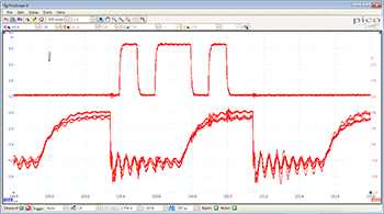 100 000 waveforms per secondAn important specification to understand when evaluating oscilloscope performance is the waveform update rate, which is expressed as waveforms per second. While the sample rate indicates how frequently the oscilloscope samples the input signal within one waveform, or cycle, the waveform capture rate refers to how quickly an oscilloscope acquires waveforms. Oscilloscopes with high waveform capture rates provide better visual insight into signal behavior and dramatically increase the probability that the oscilloscope will quickly capture transient anomalies such as jitter, runt pulses and glitches – that you may not even know exist. The PicoScope 4000A Series oscilloscopes use hardware acceleration to achieve up to 100 000 waveforms per second. More information on Fast waveform update rates >> 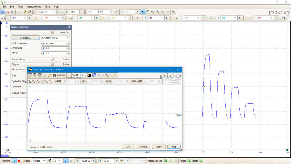
Arbitrary waveform and function generatorsAll models in the PicoScope 4000A Series have a built-in low-distortion, 80 MS/s, 14-bit arbitrary waveform generator (AWG), which can be used to emulate missing sensor signals during product development, or to stress-test a design over the full intended operating range. Waveforms can be imported from data files or created and modified using the built-in graphical AWG editor. A function generator is also included, with sine, square, and triangle waves up to 1 MHz, along with DC level, white noise, and many more standard waveforms. As well as level, offset and frequency controls, advanced options allow you to sweep over a range of frequencies. Combined with the spectrum peak hold option, this creates a powerful tool for testing amplifier and filter responses. More information on Arbitrary waveform generator (AWG) >> 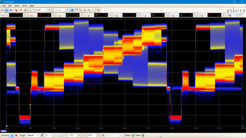
Color persistence modesAdvanced display modes allow you to see old and new data superimposed, with new data in a brighter color or shade. This makes it easy to see glitches and dropouts and to estimate their relative frequency. Choose between analog persistence, digital color, or custom display modes. More information on Persistence modes >> High-end features as standardBuying a PicoScope is not like making a purchase from other oscilloscope companies, where optional extras considerably increase the price. With our scopes, high-end features such as resolution enhancement, mask limit testing, serial decoding, advanced triggering, automatic measurements, math channels, XY mode, segmented memory, and a signal generator are all included in the price. To protect your investment, both the PC software and firmware inside the scope can be updated. Pico Technology has a long history of providing new features for free through software downloads. We deliver on our promises of future enhancements year after year, unlike many other companies in the field. Users of our products reward us by becoming lifelong customers and frequently recommending us to their colleagues. 
PicoScope performance and reliabilityWith over 25 years’ experience in the test and measurement industry, we know what’s important in an oscilloscope. The PicoScope 4000A Series delivers value for money by including a wide range of high-end features as standard. The PicoScope 6 software includes serial decoding and mask limit testing, and new functionality is regularly delivered through free upgrades to ensure that your device does not quickly become outdated. All Pico Technology devices are optimized with the help of feedback from our customers. Zoom in and capture every last detailThe PicoScope zoom function lets you take a closer look at the fine detail on your signals. Using simple point-and-click tools you can quickly zoom in on both axes and reveal every last detail of the signal, whilst the undo zoom function lets you return to the previous view. USB connectivityThe SuperSpeed USB 3.0 connection not only allows high-speed data acquisition and transfer, but also makes printing, copying, saving, and emailing your data from the field quick and easy. USB powering removes the need to carry around a bulky external power supply, making the kit even more portable for the engineer on the move. The Software Development Kit (PicoSDK®) allows unlimited data collection and fast streaming. PicoScope 4224A & 4424A oscilloscope software
|
|||||||||||||||||||||||||||||||||||||||||||||||||||||||||||||||||||||||||||||||||||||||||||||||||||||||||||||||||||||||||||||||||||||||||||||||||||||||||||||||||||||||||||||||||||||||||||||||||||||||||||||||||||||||||||||||||||||||||||||||||||||||||||||||||||||||||||||||||||||||||||||||||||||||||||||||||||||||||||||||||||||||||||||||||||||||||||||||||||||||||||||||||||||||||||||||||||||||||||||||||||||||||||||||||||||||||||||||||||||||||||||||||||||||||||||||||||||||||||||||||||||||||||||||||||||||||||||||||||||||||||||||||


| Resource | Version | Size | Last updated | |
|---|---|---|---|---|
| Data Sheet: | ||||
| PicoScope 4000A Series Data Sheet | English | 12 | 3 MB | Jan 04 2016 |
| User Guides Manuals: | ||||
| PicoScope 4000 Series User’s Guide | English | 1 | 538 KB | June 01 2018 |
| PicoScope 6 User’s Guide | English | 48 | 10MB | February 12 2018 |
| Programmer's Guide: | ||||
| PicoScope 4000 Series Programmer’s Guide | English | 9 | 1MB | June 29 2016 |
| Triggering a PicoScope signal generator using the PicoScope API functions | English | 1 | 54 KB | April 01 2015 |
| Quick Start Guide: | ||||
| PicoScope USB Oscilloscope Quick Start Guide | English Français Deutsch Italiano Español ä¸æ–‡ (简体) í•œêµì–´ 日本èª� |
1 | 1MB | March 13 2018 |
| Training Guides: | ||||
| PicoScope 6 Frequently Asked Questions | English | 3 | 949KB | August 18 2016 |
| PicoScope 6 Oscilloscope Software Training Manual | English | 3 | 8MB | October 01 2014 |
| Beginner’s Guide to PicoScope | English | 1 | 2MB | August 26 2014 |
4224A and 4424A Specifications
| Oscilloscope – horizontal | |
|---|---|
| Maximum sampling rate (real-time) | 80 MS/s (up to four channels in use) 40 MS/s (five or more channels in use) |
| Maximum sampling rate (USB 3.0, continuous streaming mode) | 20 MS/s using PicoScope 6 software, shared between channels 80 MS/s max. for a single channel using PicoSDK. 160 MS/s total across all channels. (PC-dependent) |
| Timebase ranges | 20 ns/div to 5000 s/div |
| Buffer memory | 256 MS shared between active channels |
| Streaming buffer memory (PicoScope) | 100 MS |
| Streaming buffer memory (SDK) | Up to available PC memory |
| Maximum buffer segments | 10,000 |
| Maximum waveforms per second | 100,000 (PC-dependent) |
| Timebase accuracy | ±20 ppm ( 5 ppm/year) |
| Sample jitter | 25 ps RMS typical |
| Dynamic performance (typical) | |
|---|---|
| Crosstalk | −76 dB, DC to 20 MHz |
| Harmonic distortion | < −60 dB, 10 mV range < −70 dB, 20 mV and higher ranges |
| SFDR | > 60 dB, 20 mV and 10 mV ranges > 70 dB, 50 mV and higher ranges |
| Noise | 45 μV RMS on 10 mV range |
| Bandwidth flatness | DC to full bandwidth ( 0.2 dB, −3 dB) |
| Pulse response | < 1% overshoot |
| Triggering | |||
|---|---|---|---|
| Source | Channels A to B | Channels A to D | Channels A to H |
| Trigger modes | Free run, auto, repeat, single, rapid (segmented memory) | ||
| Trigger types | Edge with adjustable hysteresis, pulse width, window, window pulse width, dropout, window dropout, interval, logic level, runt pulse | ||
| Trigger sensitivity | Digital triggering provides 1 LSB accuracy up to full bandwidth | ||
| Maximum pre-trigger capture | 100% of capture size | ||
| Maximum post-trigger delay | Zero to 4 billion samples (settable in 1 sample steps) | ||
| Trigger rearm time | < 3 μs on fastest timebase | ||
| Maximum trigger rate | Up to 10 000 waveforms in a 30 ms burst | ||
| Advanced digital trigger levels | All trigger levels, window levels and hysteresis values settable with 1 LSB resolution across input range | ||
| Advanced digital time intervals | Settable with 1 sample resolution from 1 sample (minimum 12.5 ns) up to 4 billion sample intervals | ||
| Function generator | |
|---|---|
| Standard output signals | Sine, square, triangle, DC voltage, ramp, sinc, Gaussian, half-sine, white noise, PRBS |
| Standard signal frequency | 0.03 Hz to 1 MHz |
| Sweep modes | Up, down, dual |
| Triggering | Can trigger a counted number of waveform cycles or sweeps (up to 1 billion) from the scope trigger or manually from software. |
| Frequency accuracy | ±20 ppm |
| Frequency resolution | < 0.02 Hz |
| Voltage range | ±2 V |
| Amplitude and offset adjustment | Signal amplitude and offset within ± 2V range. Adjustable in approx 300 μV steps. |
| Amplitude flatness | < 0.5 dB to 1 MHz typical |
| DC accuracy | ±1% of full scale |
| SFDR | 87 dB typical |
| Output characteristics | Rear-panel BNC, 600 Ω output impedance |
| Overvoltage protection | ±10 V |
| Arbitrary Waveform Generator | |
|---|---|
| Update rate | 80 MS/s |
| Buffer size | 16 kS |
| Resolution | 14 bits (output step size approximately 300 μV) |
| Bandwidth | 1 MHz |
| Rise time (10% to 90%) | 150 ns |
| Sweep modes, triggering, frequency accuracy and resolution, voltage range and accuracy and output characteristics as for function generator. | |
| Spectrum analyzer | ||||||
|---|---|---|---|---|---|---|
| Frequency range | DC to 20 MHz | |||||
| Display modes | Magnitude, average, peak hold | |||||
| Windowing functions | Rectangular, Gaussian, triangular, Blackman, Blackman-Harris, Hamming, Hann, flat-top | |||||
| Number of FFT points | Selectable from 128 up to 1 million in powers of 2 | |||||
| Scale / units | X axis : linear or log 10 Y axis : logarithmic (dbV, dBu, dBm, arbitrary) or linear (volts) |
|||||
| Math channels | |
|---|---|
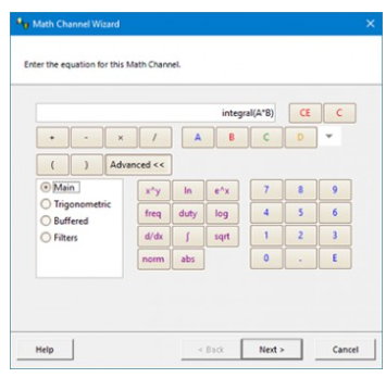
| General functions | −x, x y, x−y, x*y, x/y, x^y, sqrt, exp, ln, log, abs, norm, sign, sin, cos, tan, arcsin, arccos, arctan, sinh, cosh, tanh, derivative, integral, delay |
| Filter functions | Lowpass, highpass, bandstop, bandpass |
| Graphing functions | Frequency, duty cycle |
| Multi-waveform functions | Min, max, average, peak |
| Operands | Input channels, reference waveforms, time, constants, pi |
| Automatic measurements | |
|---|---|
| Scope mode | AC RMS, true RMS, cycle time, DC average, duty cycle, falling rate, fall time, frequency, high pulse width, low pulse width, maximum, minimum, peak to peak, rise time, rising rate. |
| Spectrum mode | Frequency at peak, amplitude at peak, average amplitude at peak, total power, THD %, THD dB, THD N, SFDR, SINAD, SNR, IMD |
| Statistics | Minimum, maximum, average and standard deviation |
| DeepMeasure™ | |
|---|---|
| Scope mode | AC RMS, true RMS, cycle time, DC average, duty cycle, falling rate, fall time, frequency, high pulse width, low pulse width, maximum, minimum, peak to peak, rise time, rising rate. |
| Spectrum mode | Frequency at peak, amplitude at peak, average amplitude at peak, total power, THD %, THD dB, THD N, SFDR, SINAD, SNR, IMD |
| Statistics | Minimum, maximum, average and standard deviation |
| Serial decoding | |||||
|---|---|---|---|---|---|
| Protocols | 1-Wire, ARINC 429, CAN, CAN FD, DALI, DCC, DMX512, Ethernet (10Base-T), FlexRay, I²C, I²S, LIN, Manchester, MODBUS (ASCII and RTU), PS/2, SENT, SPI, UART/RS-232. Subject to number of channels available. | ||||
| Inputs | All input channels with any mixture of protocols | ||||
| Mask limit testing | |
|---|---|
| Mask creation | User-drawn, table entry, auto-generated from waveform or imported from file |
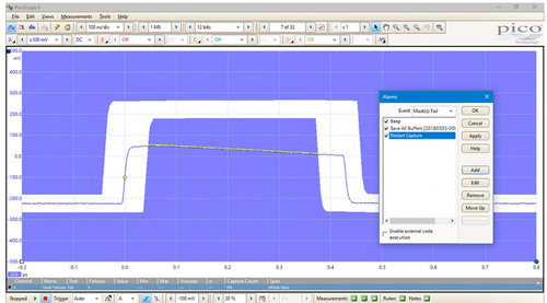
| Actions | Highlight on screen, select in buffer overview, activate alarm |
| Statistics | Pass/fail, failure count, total count |
| Alarms | |
|---|---|
| Initiating events | Capture, buffer full, mask fail |
| Alarm actions | Beep, play sound, stop/restart capture, run executable, save current buffer/all buffers, trigger signal generator |
| Display | |||||
|---|---|---|---|---|---|
| Interpolation | Linear or sin(x)/x | ||||
| Persistence modes | Digital color, analog intensity, fast, custom | ||||
| Data export | |
|---|---|
| Output file formats | BMP, CSV, GIF, JPG, MATLAB 4, PDF, PNG, PicoScope data, PicoScope settings, TXT |
| Output functions | Copy to clipboard, print |
| Environmental | ||
|---|---|---|
| Temperature range (operating) | 0 °C to 45 °C | |
| Temperature range (stated accuracy) | 20 °C to 30 °C | |
| Temperature range (storage) | –20 °C to 60 °C | |
| Humidity range (operating) | 5% to 80% RH non-condensing | |
| Humidity range (storage) | 5% to 95% RH non-condensing | |
| Altitude | Up to 2000 m | |
| Pollution degree | EN 61010 pollution degree 2: “only nonconductive pollution occurs except that occasionally a temporary conductivity caused by condensation is expected” | |
| Physical properties | |
|---|---|
| Dimensions | 190 x 170 x 40 mm (7.5" x 6.7" x 1.6") |
| Weight | < 0.55 kg (19.4 oz) |
| Software | ||
|---|---|---|
| Windows software | PicoScope 6 PicoLog 6 PicoSDK software development kit Windows 7, 8 or 10 recommended (read more) |
|
| macOS software | PicoScope 6 Beta (feature list) PicoLog 6 Software development kit (SDK) OS versions: see release notes |
|
| Linux software | PicoScope 6 Beta (feature list) Software development kit (SDK) See Linux Software & Drivers for details of supported distributions |
|
| Raspberry Pi software | PicoLog 6 for Raspberry Pi 3B and 4B (Raspberry Pi OS) | |
| Languages | PicoScope 6: English, Chinese (simplified), Chinese (traditional), Czech, Danish, Dutch, Finnish, French, German, Greek, Hungarian, Italian, Japanese, Korean, Norwegian, Polish, Portuguese, Romanian, Russian, Spanish, Swedish, Turkish PicoLog 6: English (UK), English (US), Simplified Chinese, Dutch, French, German, Italian, Japanese, Korean, Russian, Spanish |
|
| General | ||||||
|---|---|---|---|---|---|---|
| What's in the box? | PicoScope 4000A Series high-resolution oscilloscope USB 3.0 cable USB Oscilloscope Quick Start Guide 10:1/1:1 switched probes (quantity shown below) |
|||||
| Number of probes included | 2 | 4 | 4 | |||
| PC connectivity | SuperSpeed USB 3.0 (USB 2.0 compatible) | |||||
| Power requirements | Powered from USB | |||||
| Ground terminal | M4 screw on rear panel | |||||
| Safety compliance | Designed to EN 61010-1; LVD compliant | |||||
| EMC compliance | Tested to meet EN61326-1 and FCC Part 15 Subpart B | |||||
| Environmental compliance | RoHS and WEEE | |||||
| Total satisfaction guarantee | ||||||
| Oscilloscope – vertical | |||
|---|---|---|---|
| Input channels | 2 | 4 | 8 |
| Bandwidth (−3 dB) | 20 MHz (50 mV to 50 V ranges) 10 MHz (10 mV and 20 mV ranges) |
||
| Rise time (calculated) | 17.5 ns (50 mV to 50 V ranges) 35.0 ns (10 mV and 20 mV ranges) |
||
| Input type | BNC, at least 20 mm spacing | ||
| Vertical resolution | 12 bits | ||
| Software-enhanced vertical resolution | Up to 16 bits | ||
| Input sensitivity | 2 mV/div to 10 V/div (10 vertical divisions) | ||
| Input ranges | ±10 mV to ±50 V full scale, in 12 ranges | ||
| Input coupling | Software-selectable AC / DC | ||
| Input characteristics | 1 MΩ âˆ¥ 19 pF | ||
| DC accuracy | ±1% of full scale ±300 μV | ||
| Analog offset range (vertical position adjustment) | ±250 mV (10 mV to 500 mV ranges) ±2.5 V (1 V to 5 V ranges) ±25 V (10 V to 50 V ranges) |
||
| Analog offset accuracy | ±1% of offset setting additional to basic DC accuracy | ||
| Maximum input voltage | ±50 V DC, 42.4 V peak AC | ||
| Overvoltage protection | ±100 V (DC AC peak) | ||
Order your 4224/4424 PicoScope Online:
|
*Login to order. |
4224A - (PQ288 Scope & Software) |
Order your PQ288 Here: |
|---|---|---|
|
*Login to order. |
4424A - (PQ289 Scope & Software) |
Order your PQ289 Here: |
| *Login to order. | 4824A - Kit - (PQ290) 8 Channel Scope 8 Channel, 20 MHz Oscilloscope with 8 Probes |
Order your PQ290 Here: |
| 4824A | Order your PQ290_4 Here: |
|
| 4824A | Order your PQ290_8 Here: |
|
| *Login to order. | 4262 - 2 Ch 16 Bit (PP799) 2 Channel 16bit, 5 MHz Oscilloscope with 2 Probes |
Order your PP799 Here: |
|
4224-IEPE (PP695 - Call us re this unit 1-877-902-2979): |
|
Passive oscilloscope probe: 100 MHz bandwidth 1:1/10:1 switchable, BNC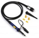
TA375
Order:
 |
 |
|||
|
|
|
 |