|
 |
|
MSR valve-tester plug-in module
|
back |
The valve tester measures the delay time between the control pulse and the output signal. It logs this time together with the value of the output signal and a time stamp. In addition, the delay time is analysed.
| Measured parameters: |
Voltage
Delay time between control pulse and output signal
Analysis of the delay time during the test |
| Measurement range: |
Voltage: 0-2.7 V
Delay time: 0-30 000 ms
Counter: 23 Bit |
| Resolution: |
Voltage: 12 bit
Delay time: 1 ms
Counter: 1 bit |
| Measurement rate: |
Selectable - up to 10 kHz |
| Storage rate: |
All measured delay times |
| Mode of operation: |
Each measured delay time is recorded and logged together with the output signal |
| Input: |
4 analogue inputs for optional use as
- Voltage input
- Analogue pressure input
- Digital input 0-10 V
- Digital optoelectronic coupler input
- Digital input with photo diode
Each input can be defined as a control pulse of a output signal |
| Storage capacity: |
1 000 000 measurements |
| Integration with MSR: |
By qualified personnel |
| Item number: |
B10106 |
| Accessories: |
Dockingstation DS1 B10135 Fig. |
| Attachable sensors: |
| Sensors |
Item number |
| Pressure sensor PA-21SR/16bar Fig. |
S10015 |
| Optoelectronic coupler DS1 IF OPTO Fig. |
B10136 |
| Photo diode DS1 IF FOTO |
B10139 |
|
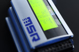
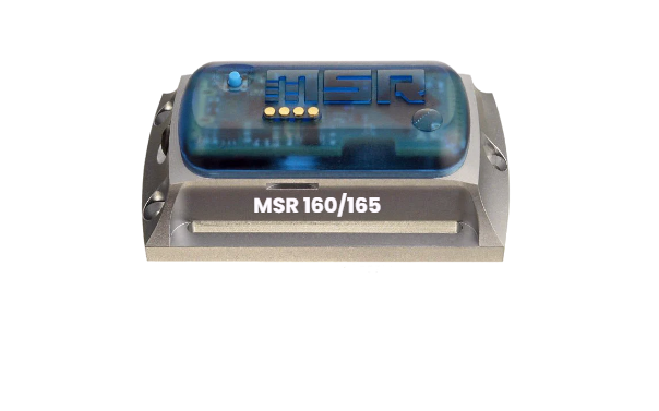
Fig. MSR plug-in module valve-tester
Module Datasheet 
 |
|
|
|
|
|