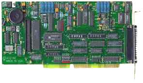
The Al216E is a 3/4-1ength, multifunction, high-speed analog/digital I/O card for use in ISA-bus Computers and compatibles. With this card installed, the computer can be used as a precision data acquisition and control system or a signal analysis instrument. All connections are made through standard 37-pin D type connectors at the rear of the computer. An additional 24 lines of digital I/O are accessible through a 40-pin IDC type auxiliary connector that mounts on an adjacent mounting bracket.
ANALOG INPUTS
The card accepts up to eight differential or sixteen single-ended analog inputs. The channel input configuration is switch selectable on the card, providing a choice between sixteen single-ended channels or eight differential channels. Analog inputs may be configured in unipolar (0 - 10V) or bipolar ( ±5V and ±10V) modes through the use of jumpers on the card. These inputs are amplified by a low-bias-current, fast-settling, monolithic instrumentation amplifier with high common-mode rejection. The amplifier provides programmable gains of 1, 10, 100, and 1000 and settles to 0.01% in 2 µSec.
The A1216E card uses a 12-bit successive approximation analog-to-digital converter (A/D) with a sample and hold amplifier input. Under ideal conditions, the A/D can sustain a rate of 100,000 conversions per second. A/D conversions may be initiated in one of three ways:
- by software command,
- by on-board programmable timer, or
- by direct external trigger.
Data may be transferred to the computer by interrupt or program control. Interrupt levels 2-7 as well as 10, 11, 12, 14, and 15 are available by jumper selection.
INPUT SYSTEM EXPANSION
The card can be used with up to sixteen AIM-16P analog input multiplexer cards. Each AIM-16 provides capability to connect sixteen differential inputs. Thus, when an A1216E is used with a full complement of AIM-16's, there can be as many as 256 analog inputs. Use of an AIM-16 with the A1216E requires a special cable adaptor.
ANALOG OUTPUTS
The A1216E card has two 12-bit digital-to-analog converters (D/A) connected to output drivers capable of providing 5 mA current drive. Each channel provides output ranges of 10V, 5V, and 2.5V unipolar and ±l0V, ±5V, ±2.5V bipolar. The ranges of the two D/A's are independent and are selected by means of switches on the card. The D/A's make use of an on-board reference voltage. Analog outputs are disabled at power-up and remain disabled until the computer writes to them. This prevents spurious outputs from causing damage when the system is first activated.
DIGITAL I/O
Four bits of TTL/CMOS- compatible digital input capability are provided. Digital inputs IP0 and IP2 have dual purposes. Input IP0 may be used to provide external start pulses to the A/D. Input IP2 may be used as a gate input to Counter/Timer 0. These inputs can be converted to output ports for multiple AIM-16 applications as described under Input System Expansion. When this is done, you give up capability for external triggering of the A/D and gating Counter/Timer 0.
Four bits of digital output are available with LSTTL logic levels and 10 LSTTL load drive capability. Discrete outputs OP0 through OP3 provide multiplexer addressing capability for input expansion use, as described previously, or can be used as separate digital outputs. There are twenty-four bits of additional digital I/O available on the auxiliary connector. These bits are arranged in two 8-bit ports and two 4-bit ports. Each port may be independently programmed for input or output.
COUNTER/TIMERS
Three 16-bit Counter/Timers are provided on the A1216E. Counter/Timer 0 is enabled by a digital input and uses either an internal 1 .0 MHz clock or an external clock of up to 10 MHz. This counter is not committed on the card. Its clock, enable, and output lines are all available at the I/O connector. Counter/Timers 1 and 2 are concatenated to form a 32-bit counter/timer for timed A/D conversions and/or external frequency generation. This dual counter/timer is enabled by program control and is clocked by a 1 MHz on-board crystal oscillator source. Counter/Timer 0 and Counter/Timers 1 and 2 can be set up for event counting, frequency or period measurements, and pulse or waveform generation.
PIN CONNECTIONS
Connections are made to the A1216E card via a 37-pin D type connector that extends through the back of the computer case. The only differences between the A1216E and the AD12-16/16F are the absence of analog reference inputs and the -5V reference output since analog output ranges are selected by on-board jumpers.
Specifications

Analog Inputs
- Channels: 16 single-ended or 8 differential, switch selectable.
- Resolution: 12 binary bits.
- Accuracy: 0.1%.
- Input Voltage Modes: ±5V, ±10V, 0-10V
- Input Amplifier Gains: 1, 10, 100, 1000 (Under software control per channel).
- Coding: True binary for unipolar inputs and offset binary for bipolar inputs under jumper control.
- Conversion Time: 8 usec max. (100 KHz throughput)
- A/D Type: Successive Approximation.
- Monotonicity: Guaranteed over operating temperature range.
- Linearity: ±0.9 LSB.
- Zero Drift: ±2 PPM/°C.
- Gain Drift: ±2 PPM/°C.
- Trigger Source: Software Command, On-board Programmable Timer, or External Source.
Analog Outputs
- Channels: Two, independent.
- Type: 12-bit, double-buffered.
- Relative Accuracy: ±1 LSB.
- Output Ranges: 0-2.5V, 0-5V, 0-10V, 2.5V, ±5V, ±10V.
- Settling Time: 15 usec to ± 1 bit.
- Output Drive: 5 mA.
- Output Impedance: 0.5 ohms.
Digital I/0
(8 Bits on Main 37-Pin D Connector)
Inputs:
- Logic High: 2.0 to 5.0 VDC at 20 uA max.
- Logic Low: -0.5 to 0.8 VDC at -0.2 mA max.
Outputs:
Digital I/O
(24 Bits on Auxiliary 40-Pin IDC Connector)
Inputs:
Outputs:
Programmable Timer
- Type: 82C54-2 programmable interval timer.
- Counters: Three 16-bit down counters, two concatenated with 1 MHz clock as programmable timer. One counter may be driven by an external input to 10 MHz or driven by internal 1 MHz clock source.
- Output Drive: 2.2 mA at 0.45V (5 LSTTL loads).
- Input Gate: TTL/DTL/CMOS compatible.
- Clock Input Frequency: DC to 10 MHz.
- Active Count Edge: Negative edge.
- Minimum Clock Pulse Width: 30 nS high/50 nS low.
- Timer Range: 2.5 MHz to < 1 pulse per hour.
Environmental
- Operating Temperature Range: 0° to 50°C.
- Storage Temperature Range: -20° to 70°C.
- Humidity: 0 to 90% RH, non-condensing.
- Weight: 10 oz.
- Power Required: 5 VDC, 800 mA.
Size
Regulatory Compliance
- This product is in full compliance with CE requirements.