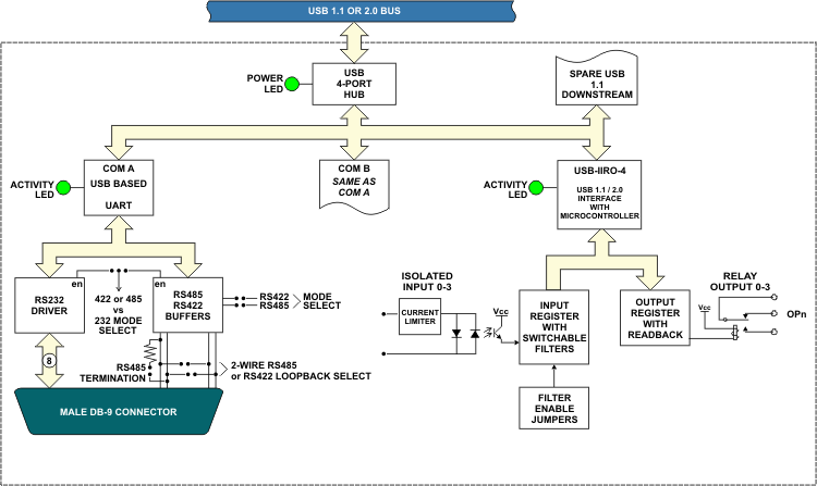
The USB-IIRO4-2SM is a USB multifunction device, incorporating a USB 4-port hub internally to provide four optically isolated digital inputs, four electromechanical relay outputs and two ports of RS-232/422/485 serial communication in one small product. The digital portion is ideal for adding easy-to-install isolated input and relay output capabilities to any PC or embedded system with a USB port. This single USB multifunction device is ideal for a variety of applications such as industrial monitoring, control and communication.
DIGITAL
The isolated, non-polarized inputs may be driven by either DC sources of 3-31 V (or higher by special order) or AC sources at frequencies of 40Hz to 10kHz. Optically isolating the digital inputs from each other, and from the computer, assures smooth, error-free data transmission in noisy, real-world environments. The relay outputs are de-energized at power-up to prevent an unintended control output signal. Data to the relays is latched. The relay contacts and isolated inputs are available via a mounted DB25 connector or, for OEMs, a 26-pin IDC type vertical keyed shrouded header. For testing purposes and low current applications 5VDC and ground pins are provided on the same connector. The digital portion of the USB-IIRO4-2SM is excellent in applications where only a few on-board relays are required and a small number of inputs must be isolated such as in test equipment, instrumentation and process control.
SERIAL
The serial section is a two-port asynchronous serial communication adapter designed for use with any computer system equipped with a USB port. Multiple peripherals such as POS, barcode scanners, scales, date-entry terminals, data acquisition modules, and automation equipment can now be recognized and used on a single USB port. Simply install the included software and connect the unit to your USB port. It instantly provides two RS-232, RS-422, or RS-485 serial ports which can be selected on a port by port basis. It is now easier than ever to add serial ports and serial devices to any application along with easy plug-and-play and hot-swapping features.
Type FT232 UARTs are used as asynchronous communication elements. This includes 384-byte receive / 128-byte transmit FIFO buffers for high data throughput and to protect against lost data in multitasking systems. Crystal oscillators located on the card permit precise baud rate capability up to 230.4K for use in RS-232 mode, using ICL3243 type drivers. Speeds up to 921.6K are achievable using RS-422 & RS-485. The driver/receivers used are type SP491 which are capable of driving long communication lines at high baud rates. They can drive up to ±60 mA on balanced lines and receive inputs as low as 200 mV differential signal superimposed on common mode noise of 12V to -7V. In case of communication conflict, the driver/receivers feature thermal shutdown. The serial communications are conveniently provided through two DB9 board mounted male connectors with adjacent LEDs indicating serial port activity.
ENCLOSURE
The USB-IIRO4-2SM includes a rugged steel enclosure with attractive powder coat finish and anti-skid bottom. The unit enclosure is 4 inches wide by 4 inches deep by 1.8 inches high. The adapter is supplied with a 6 foot USB cable. In addition to the two serial LEDs the unit features two additional easy-to-read LEDs indicating digital I/O enabled/ready and USB power. Port protocol is configured by opening the enclosure and configuring jumpers on the circuit board. It is fully compatible with both USB 1.1 and USB 2.0 ports. The OEM version provides just the board without the enclosure and is ideal for a variety of embedded OEM applications.
OEM USB/104 FORM FACTOR
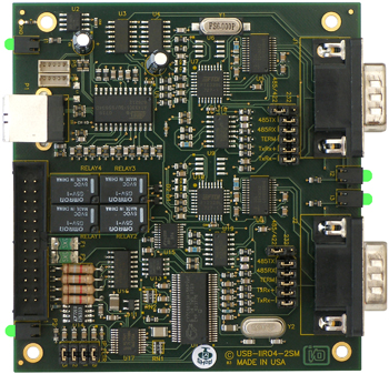
What makes the OEM option unique is that its PCB size and mounting holes match the PC/104 form factor (without the bus connections). This allows our rugged digital/serial board to be added to any PCI-104 or PC/104 stack by connecting it to a simple USB port usually included on-board with embedded CPU form factors such as EBX, EPIC, and PC/104 - especially important since many newer CPU chipsets do not support ISA and have plenty of USB ports. Future stacks will be using the extremely fast PCI Express bus which is essentially overkill for simple digital monitoring and control. The USB-IIRO4-2SM OEM board can also be added into many pre-existing standard PC/104 based systems and enclosures.
High Retention USB Connector
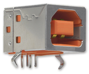
The ever-growing presence of USB in the industrial/military marketplace has driven the need for USB connections to be reliable, dependable, and unfailing. Gone are the days of lose USB connections. A type B USB connector is used on all ACCES USB/104 products which features a high retention design that complies with the class 1, Div II minimum withdrawal requirement of over 3 pounds of force (15 Newtons). This connector has an orange color-coded insulator to quickly differentiate it from standard USB connectors. Using these USB connectors increases reliability in your system and ensures a tight connection. For embedded OEM type applications, an additional miniature USB input header is provided in parallel with the type B connector.
APPLICATIONS
The industrial I/O market commonly uses electromechanical Form C relays due to their robustness and ability to withstand unexpected surge currents allowing for increased flexibility in switching capability. These relays are also used where small reed relays are inadequate due to their susceptibility to contact damage. The USB-IIRO4-2SM with its tiny enclosure and easy connectivity provides portable connections to laptops for this kind of monitoring and control for the mobile test market. The full USB-IIRO4-2SM unit can be used in the following markets.
- Home
- Portable and laptop
- Education
- Industrial Automation and Control
- Embedded OEM
- Point of Sale (POS) Retail
- Data Acquisition
- Serial Instrumentation
- Laboratory Research
- Remote Access
ACCESSORIES
The USB-IIRO4-2SM is available with optional cable assemblies, screw termination boards and DIN rail mounting provisions.
SOFTWARE
The USB-IIRO4-2SM is plug-and-play which allows quick connect or disconnect whenever you need additional I/O on your USB port. The USB-IIRO4-2SM is supported for use in most USB supported operating systems and includes a free Linux and Windows 98se/Me/2000/XP/2003 compatible software package. This package contains sample programs and source code in Visual Basic, Delphi, C Builder, and Visual C for Windows. Also incorporated is a graphical setup program in Windows. Third party support includes a Windows standard DLL interface usable from the most popular application programs. Embedded OS support include Windows Xpe.
For serial communications the package includes an easy to use terminal program for testing out your COM ports. Use in other operating systems may also be supported, contact Factory.
Specifications
| IIRO Connector Pin Assignments |
| Pin # |
Signal Name |
|
Pin # |
Signal Name |
| 1 |
Input 0 A |
|
14 |
Relay 0 NO |
| 2 |
Input 0 B |
|
15 |
Relay 0 Common |
| 3 |
Input 1 A |
|
16 |
Relay 0 NC |
| 4 |
Input 1 B |
|
17 |
Relay 1 NO |
| 5 |
Input 2 A |
|
18 |
Relay 1 Common |
| 6 |
Input 2 B |
|
19 |
Relay 1 NC |
| 7 |
Input 3 A |
|
20 |
Relay 2 NO |
| 8 |
Input 3 B |
|
21 |
Relay 2 Common |
| 9 |
Ground |
|
22 |
Relay 2 NC |
| 10 |
Ground |
|
23 |
Relay 3 NO |
| 11 |
5 V |
|
24 |
Relay 3 Common |
| 12 |
5 V |
|
25 |
Relay 3 NC |
| 13 |
No Connect |
|
26 |
No Connect |
| Serial Connector Pin Assignments |
DB-9 Male Pin for
each of Ch A-G |
RS-232 Signals
(Industry Standard) |
RS-485 Signals
(2 Wire) |
RS-422 Signals
(Also 4wire RS485) |
| Ch x - 1 |
DCD |
RX-/TX- |
RX- |
| Ch x - 2 |
RX |
TX /RX |
TX |
| Ch x - 3 |
TX |
TX-/RX- |
TX- |
| Ch x - 4 |
DTR |
|
|
| Ch x - 5 |
Gnd |
Gnd |
Gnd |
| Ch x - 6 |
DSR |
|
|
| Ch x - 7 |
RTS |
|
|
| Ch x - 8 |
CTS |
|
|
| Ch x - 9 |
RI |
RX /TX |
RX |
Digital Specifications
Isolated Inputs
- Number of inputs: 4
- Type: Non-polarized, optically isolated from each other and from the computer (CMOS compatible)
- Voltage Range: 3 to 31 DC or AC Rms (40 to 10000 Hz)
- Isolation: 500V*(see note) channel-to-ground or channel-to channel
- Input Resistance: 1.8K ohms in series with opto coupler
- Filter Response Times: Rise Time = 4.7 mS / Fall Time = 4.7 mS
- Non-Filter Response Times: Rise Time = 10 uS / Fall Time = 30 uS
*Notes on Isolation: Opto-Isolators and connectors are rated for at least 500V, but isolation voltage breakdowns will vary and is affected by factors like cabling, spacing of pins, spacing between traces on the PCB, humidity, dust and other environmental factors. This is a safety issue so a careful approach is required. For CE certification, isolation was specified at 40V AC and 60V DC. The design intention was to eliminate the influence of common mode. Use proper wiring techniques to minimize voltage between channels and to ground. For example, when working with AC voltages do not connect the hot side of the line to an input. Tolerance of higher isolation voltage can be obtained on request by applying a conformal coating to the board.
Relay Outputs
- Number of outputs: 4 SPDT form C
- Contact Type: Single crossbar; Ag with Au clad
- Rated Load AC: 0.5 A at 125 VAC (62.5 VA max.)
- Rated Load DC: 1A at 24 VDC (30 W max.)
- Max. Switching Voltage: 125 VAC, 60 VDC
- Max. Switching Current: 1 A
- Contact Resistance: 100 mO max.
- Contact Life: mech'l: 5 million operations min.
- Operating Time: 5 milliseconds max.
- Release Time: 5 milliseconds max.
Communications Interface
- I/O Connections: There are 9 pins per port including common grounds. All RS-232 signals are supported and present at the DB9 connectors.
- RS-422 data signals – Tx , Tx-, Rx , Rx-, GND
- RS-485 data signals – 2 wire: Tx/Rx , Tx/Rx-, GND
- 4 wire: Tx , Tx-, Rx , Rx-, GND
- Jumper selectable termination
- Serial Data Rates: Up to 230.4K bps, asynchronous for RS-232
- Up to 921.6K bps, asynchronous for RS-422 & RS-485.
- Multidrop: Compatible with RS-485 specifications. Up to 32 drivers and receivers allowed on line. Driver / Receivers used are type SP491.
- Character Length, Parity and Stop Interval: 5,6,7, or 8 bits; Even, odd, or none; 1, 1.5, or 2 bits
- Receiver Sensitivity: ±200 mV differential input
- Common Mode Voltage: 12V to -7V
- Transmitter Output Drive: 60 mA with thermal shutdown
- Termination: Jumper selectable per channel for RS-485 mode
- Bias: On-board from factory on transmit lines for RS-485 & RS-422
Bus Type
USB 1.1 and 2.0 host compatible
Power Required
- 5V@ 120mA Quiescent, 320mA maximum
- 20mA for each activated relay(80 max)
- 0-60mA for each COM channel
- 5VDC provided via USB cable up to 500mA
Environmental
- Operating Temperature Range: 0°C. to 60°C.
- Storage temperature Range: -50°C. to 120°C.
- Humidity: 5% to 95%, non-condensing.
- Size: 4 inches wide by 4 inches deep by 1.8 inches high
Extra USB connections
This board has two optional USB onboard five pin connectors. One connector allows you the added feature of connecting to a spare USB port on the onboard USB1.1 hub. This would provide an additional, 'daisy-chained' USB 1.1 bus to which you can attach an additional ACCES I/O USB product or any 3rd party USB devices you may wish. Up to 180mA is still available without requiring the added device to have its own 5VDC power source. The second five pin connector allows the board to have an onboard USB connection rather than the standard type B connector that is accessible externally on the enclosure. This is useful in OEM embedded or high vibration applications where a tighter fit USB connection is required than a standard USB plug.
Regulatory Compliance
- This product is designed to be in full compliance with CE requirements.