|
|
||||
| Log In | ||||
|
| ||||
| ||||
| ||||
| ||||
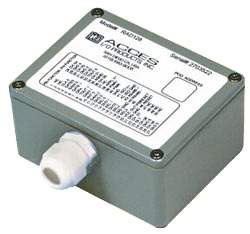
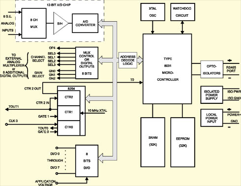
FUNCTIONAL DESCRIPTIONRAD128 is an intelligent, eight channel, 12-bit, analog-to-digital converter unit that interfaces to a host computer through an opto isolated asynchronous serial port. It is packaged in a steel enclosure for remote installation and input connections are via screw terminals on the card. Communication with the host computer is via EIA RS485 serial communications. ASCII-based command/response protocol permits communication with virtually any computer system that has an RS485 port. ASCII-based programming permits you to write applications in any high-level language that supports ASCII string functions. As many as 31 RAD128's may be connected on a single two or four wire multi-drop network. Each unit has a unique address and communication uses a master/slave protocol wherein the unit talks only if questioned by the computer. The unit's address is programmable from 00 to FF hex and whatever address is assigned is stored in EEPROM and used as the default address at the next power-on. Similarly, baud rate is programmable for 1200, 2400, 4800, 9600, 14400, 19200, and 28800. The programmed baud rate is stored in EEPROM and used as default at the next power-on. A type 8031 microcontroller (with 32K x 8 bits RAM and 32K x 8 bits EEPROM and a watchdog timer circuit) gives RAG128 the capability and versatility expected from a modern distributed control system. RAD128 contains low power CMOS circuitry, an opto-isolated receiver/transmitter, and power conditioners for local and external isolated power. It can communicate at baud rates up to 28.8K baud and distances up to 4000 feet with low-attenuation twisted pair cabling. RAD128 accepts up to eight single-ended analog inputs. Input voltage ranges of ±10V, ±5V, 0-10V, and 0-5V are programmable on a channel-by-channel basis. All inputs are internally protected up to 16.5V. The digitizer used is a 12-bit, successive approximation analog-to-digital converter capable of 10,000 conversions per second. Conversions may be initiated in one of three ways: a. By software command. The RAD128 can be used alone or it may be used with signal conditioners and analog sub-multiplexers AIM-16 and LVDT-8 or with simultaneous sample and hold amplifiers models SSH-04 and SSH-08. Analog InputsThe RAD128 accepts up to eight single-ended analog inputs. Input ranges of ±10V ±5V, 0-10V, and 0-5V are programmable on a channel-by-channel basis and all inputs are overvoltage protected up to ±16.5V. RAD128 uses a 12-bit successive approximation analog-to-digital converter (A/D) capable of 10K samples per second (6.67K samples per second in background.) A/D conversions may be initiated in one of three ways: (a) by software command, (b) by an on-board programmable timer, or (c) by an external trigger. For applications that require more than eight input channels, the RAD128 is fully compatible with AIM-16P analog input expansion multiplexers. Each AIM-16P provides capability to connect sixteen differential or single-ended inputs. As many as 32 differential or single-ended inputs can be accepted when an RAD128 is used with two AIM-16P's. (For NEMA 4 installations, see the description of RIDACS systems. The RAD128 is also fully compatible with the LVDT-8 signal conditioning card for linear displacement measurements. Digital I/OEight bits of TTL/CMOS-compatible digital I/O are provided. These can be configured on a bit-by-bit basis as either inputs or outputs. When used as outputs, a maximum of seven bits is available. Each output provides compliance with user-supplied voltages up to 50V and the maximum current per output bit is 350 mA. For the seven-bit group, there is a maximum combined total of 650 mA current. There are an additional eight bits that are used strictly for digital output. Output bits G0-G2 and SEL0-SEL3 are normally used for gain and channel select when using RAD128 with an AIM-16 multiplexer board. The final output, 0P4, is available for general use. Each output has 10 LSTTL load drive capability. Counter/TimersThree 16-bit Counter/Timers are provided on the RAD128. Counter/Timer 0 is enabled by a digital input and may be clocked either by the output of Counter 1 or by an external source up to 10 MHz. This counter is not committed on the card and its clock, gate, and output lines are available at the I/O connector. Counter/Timers 1 and 2 are concatenated to form a 32-bit counter/timer for timed A/D conversions. Counter 1 may be enabled by a digital input and is clocked by an on-board, crystal-controlled 10 MHz oscillator. The output of Counter 1 provides the clock for Counter 2 and is also available at the I/O connector. The output of Counter 2 is connected to input T0 of the microprocessor and provides the means to initiate timed A/D conversions. Watchdog TimerThe built-in watchdog timer resets RAD128's microcontroller "hangs up" or if the local power supply drops below 7.5 VDC. I/O ConnectionsThere is a screw terminal assembly inside the top cover of the pod and a gland is provided to seal wiring for full NEMA compliance. You can assemble a cable of whatever length you need, route it through the gland, and terminate the cable at the other end by whatever means best fits your application. I/O Screw terminal assignments are listed in the label on the cover of the pod. PowerRAD128 contains CMOS low power circuitry, an optically isolated receiver/transmitter, and voltage regulators for local power and external isolated power. The isolated section of the unit accepts 7.5 to 35 VDC and only uses about 40 milli-amperes (7 mA at 12 VDC). This power could be provided by the computer's 12 VDC supply. Voltage drop in the cable will be insignificant, even if the cable is very long because so little current is drawn. Power for the rest of the unit's circuits can be provided by a separate, local power supply. Only 7.5 VDC is needed but, because onboard voltage regulators are provided, the local power can be as high as 18 VDC. 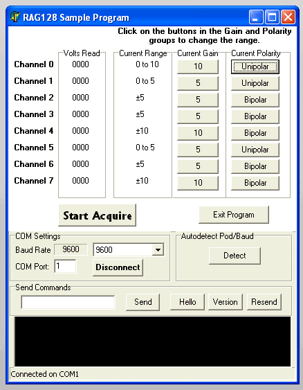
Specifications
Regulatory Compliance
View / Download Manual (in .pdf format)
|
||||||||||||||||||||||


