Log In


CAN Test Box

can test box


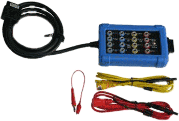
Continuing with our mission to make vehicle diagnostics easier and faster…the new CAN Test Box gives you easy access to the 16 pins of the diagnostic connector that is fitted to all modern vehicles. Depending on the configuration of the vehicle, this may allow you to check power, ground and CAN Bus signal quality. With the test leads supplied you can connect your PicoScope lab scope to the CAN Test Box to monitor signals such as the CAN High and Low. More.....

Celebrating 45 Years

Follow us on Facebook for all the latest news, updates and promotions


We have just posted a few new Automotive Tutorials and Case studies Here is the latest:
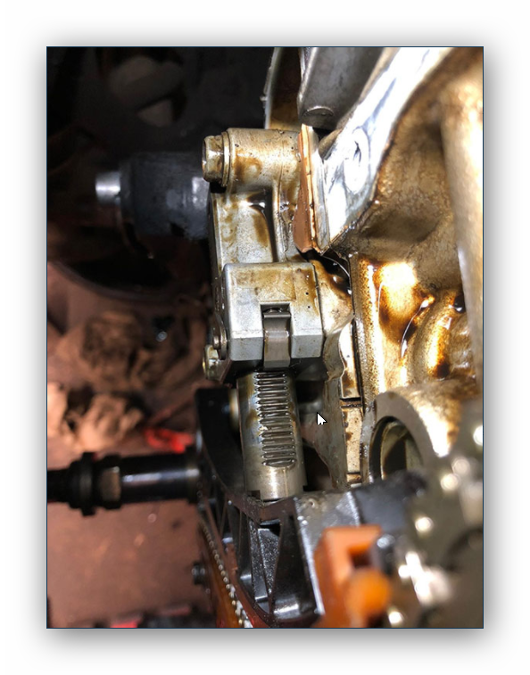
Honda Rattle

Credit Cards Accepted


Aurora Probability in Northern Canada

Auroral forecast from AuroraWatch.ca


North America Aurora Map from
NOAA Space Weather Prediction Center

Aurora Map - NOAA


Large Jaw 30 Ampere Current Clamp
[TA189]

logo

[REPLACES OBSOLETE TA234]

TA189 30 AMP CURRENT CLAMP

The 30 A precision current clamp allows you to measure from 5 mA up to 30 A without cutting, disconnecting or stripping the wire. It is ideal for measuring the currents in sensors and actuators across most modern passenger and commercial vehicles.

The TA189 provides improved sensitivity, lower noise and faster response. Featuring a 25 mm jaw size this clamp is suitable for measuring battery drain over long periods. It also features an auto power-down facility to save battery life when not in use (this feature can be disabled for battery drain / shutdown current testing).

Using advanced Hall Effect sensors for improved sensitivity and high external field rejection as well as closed loop control for increased accuracy, the TA189 delivers a breakthrough in range and accuracy to meet the challenges of modern vehicles.

These current clamps have been designed for use with PicoScope oscilloscopes and feature additional screening to reduce noise pickup.  If you require current clamps for use with other oscilloscopes or multimeters then visit this link


Buy your TA189 Current Clamp Here:

Instructions

Switch On
When the probe is switched on to the required measuring range, the green LED will illuminate. The LED starts flashing when the battery voltage is too low for normal operation and
warns the user that it requires changing. This procedure is described below.

Auto Power Off
In order to save battery life, the probe will automatically switch itself off after approximately 10 minutes. To disable the Auto power off function, Switch off the probe and Switch on whilst pressing the auto zero button. The red LED will illuminate and the probe will stay on until switched off again.

Auto Zero
The output zero offset voltage of the probe may change due to thermal shifts and other environmental conditions. Select the required measuring range and to null the output voltage
depress the Auto Zero button. Ensure that the probe is away from the current carrying conductor whilst the probe is being nulled.

Current Measurement
1. Switch on the probe by selecting the required measuring range and check that the green LED is lit.
2. Connect the output lead to the oscilloscope,
3. Zero the probe using the Auto Zero button.
4. Clamp the jaws of the probe round the conductor ensuring a good contact between the closing faces of the jaws.
5. Observe and take measurements as required. Positive output indicates that the current flow is in the direction shown by the arrow on the probe.

Battery Replacement
The green or red LED will flash when the minimum operating voltage is approached. Use the following procedure:

SAFETY WARNING
Before removing the battery cover, ensure that the probe is disconnected from the oscilloscope and remote from any live electrical circuit.

Unclamp the probe from the conductor, turn it off using the On - Off switch and disconnect the output leads from external equipment.
Loosen the captive screw which secures the battery cover. Lift the cover through 30° and pull it clear of the probe body as shown in Fig 1. Replace the battery, re-fit the battery cover and fasten the screw.

Fit only Type 9 V PP3 Alkaline (MN 1604).

Electrical data

(All accuracies stated at 23°C ± 1°C)

Nominal current 30 A AC peak  or DC
Measuring range (s) 30 A
Overload capacity 500 A (60 s)
Output sensitivity 100 mV/A
Accuracy ± 1% of reading ± 2 mA
Resolution ± 1 mA
Gain variation ±0.01% of reading/°C
Frequency range1) DC to 100 kHz (0.5 dB)
Power supply 9 V Alkaline battery
PP3, MN 1604
or IEC6LR61
Load impedance (minimum) > 100 kΩ and ≤ 100 pF


General data

Conductor size 25 mm diameter
Output cable and connectors 2 m long coax terminated with safety BNC connector
Operating temperature 0°C to 50°C
Storage temperature
with Battery removed
-20°C to 85°C
   

1)Accuracy quoted is for conductor in centre of aperture

Brochures & Manuals

Listed here are the brochures, data sheets and manuals for the 30 A large jaw current clamp.

You will need a PDF reader such as Adobe Reader to view the PDF files.

Resource Version Size Last updated
30 A large jaw current clamp User Guide 1 293 kb 12 February, 2014


USA Office

Tel:1.877.902.2979-1.425.223.4311
Fax:1.877.329.4324
Address: 1480 Gulf Road, Suite 837,
PO Box 1364
Point Roberts, WA 98281

Western Canada - Vancouver BC

Tel:1.800.663.6001 or 1.604.925.6150
Fax:1.604.925.6170
Address: 2454 Haywood Ave
West Vancouver, BC V7V 1Y1

Eastern Canada - Markham, Ontario

Tel:1.800.465.0164 or 1.905.513.7027
Fax:1.877.329.4324