|
The Digital MAF Sensor is crucial in optimizing your vehicle's performance by accurately measuring air intake, ensuring efficient engine operation. Most Mass Air Flow (MAF) sensors have analogue outputs that typically vary from 0.5 V to 4.5 V (0 V or 5 V is an error condition). The output of these sensors does not, however, change linearly with air flow - scaling and corrections need to be applied by the ECU. A typical output from a non-turbo engine is shown in figure 1 below:
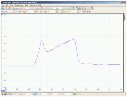
Figure 1
Some modern MAF sensors contain digital electronics so that the scaling and corrections can be made within the sensor, thus improving accuracy. The output of these sensors is a changing frequency. A typical scope trace looks like this:
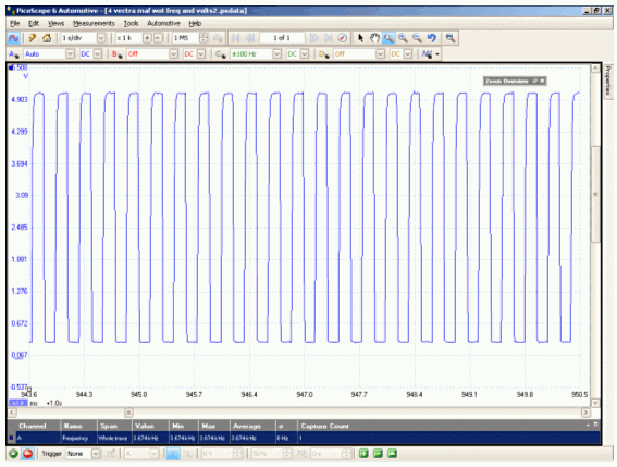
Figure 2
Whilst you can see the frequency changing with airflow, it is not as easy to test the sensor. One partial solution is to measure the current drawn by the sensor (the so called "Massey method"). A typical trace is shown below:
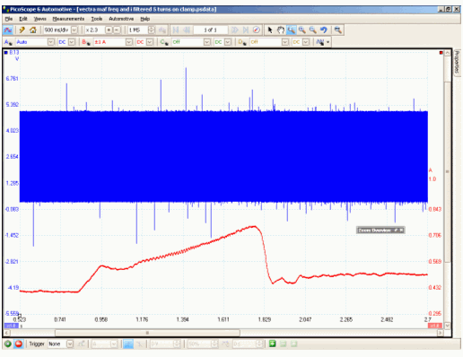
Figure 3
The blue trace shows the frequency output and the red shows the current drawn. The change in current drawn is only a few mA so it stretches the limits of what can be measured with the 60 A current clamp, even when set to the 20 A range.
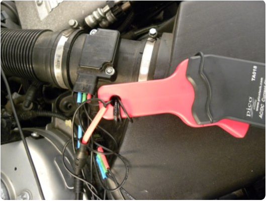
Figure 4
To get the trace below, we wrapped the wire carrying the current through the jaws of the current clamp 5 times as shown in figure 4.
This "amplifies" the current 5 times so, although the scale shows 1A, the actual range is 200 mA. We also switched on the low-pass filter to further clean up the signal.
The current clamp method will only work with hot-wire type sensors where the current drawn by the sensor is proportional to airflow. It will not work on Bosch-type hot-air film sensors or the AC Delco "coldwire" / inductive sensor as with these sensors the current does not change with airflow. Clearly a better way of testing these airflow sensors is to have an option to plot the changing frequency against time. This allows us to look at the same signal as the ECU.
An option to measure frequency against time has now been added to PicoScope software (version 6.4.28 onwards). A trace from a turbocharged diesel vehicle is shown below. The vertical scale is in frequency.
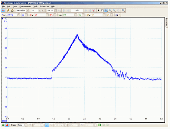
Figure 5
There are a few points to note. Firstly this option is only available on the PicoScope 4000 range of automotive scopes, as it requires hardware resources not available in earlier products. Secondly, in PicoScope 6.4.28, the frequency measurement is a bit sensitive to noise. This will be addressed in future releases. Frequency measurement is enabled from the AC/DC drop-down menu.
|