|
|
||||
| Log In | ||||
|
| ||||
| ||||
| ||||
| ||||
| ||||


 Overview Overview
8 channels, high resolution, deep memory.
Offering 8 channels and 12-bit resolution with one ADC per channel, the PicoScope 4824A delivers the functionality you need to make precision, time-correlated waveform measurements on multiple channels and a wide range of signal types. Typical Applications
Combining high resolution technology with 256 Msamples buffer memory, powerful debug tools and a built-in arbitrary waveform generator, the PicoScope 4824A is the ideal oscilloscope for precise measurements and rapid debug. Tools such as Mask Limit Testing, Serial Bus Decoding, Advanced Digital Triggers and Persistence Mode help to track problems for rapid troubleshooting. Waveforms are captured in high resolution, making it easy to distinguish signal from noise to ease debug and analysis. 8 channel oscilloscopeThe PicoScope 4824A is a low cost, portable solution for multi-input applications. 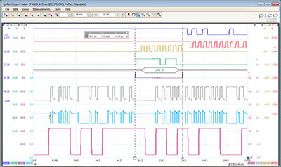
With 8 high-resolution analog channels you can easily analyze audio, ultrasound, vibration, power, and timing of complex systems, and perform a wide range of precision measurement tasks on multiple inputs at the same time. Although the scope has the same small footprint as Pico’s existing 2-and 4-channel models, the BNC connectors still accept all common probes and accessories with ample spacing of 20 mm. Despite its compact size, there is no compromise on performance. With a high 12-bit vertical resolution, bandwidth of 20 MHz, 256 MS buffer memory, and a fast sampling rate of 80 MS/s, the PicoScope 4824A has the power and functionality to deliver accurate results. It also features deep memory to analyze multiple serial buses such as UART, I2C, SPI, CAN and LIN plus control and driver signals. Applications - Power measurements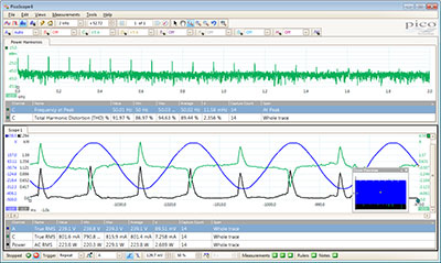
The PicoScope 4824A is ideal for making a range of power measurements on high voltages and currents and low-voltage control signals. For the best results, use a Pico differential voltage probe (TA041 or TA057) in combination with a current clamp (TA167). To improve the efficiency and reliability of power designs, the scope can display and analyze standby power dissipation, inrush current and steady-state power consumption. PicoScope’s built-in measurements and statistics of parameters such as true RMS, frequency, peak-to-peak voltage and THD allow accurate analysis of power quality. Data AcquisitionWith 256 Msamples of buffer memory the scope can capture over 5 minutes of continuous 50/60 Hz waveform data with high timing resolution. Using the Software Development Kit (SDK) you can write custom applications with storage limited only by the PC hard disk size. Nonlinear loads and modern power-conversion equipment produce complex waveforms with significant harmonic content. These harmonics reduce efficiency by causing increased heating in equipment and conductors, misfiring in variable speed drives, and torque pulsations in motors. The 12-bit PicoScope 4824A has the precision to measure distortion typically up to the 100th harmonic. On the supply side, power quality issues such as sags and dips, swells and spikes, flicker, interruptions and long-term voltage and frequency variations can also be checked for regulatory compliance. In a 3-phase distribution system, it is important to characterize and balance loads across phases. With 8 channels the PicoScope 4824A can monitor waveforms of current and voltage on all 4 conductors of a 3-phase plus-neutral system. This helps to identify mismatches that can cause breaker tripping, or transformer and conductor overheating. Applications - Complex embedded systemsWhen debugging an embedded system with a scope, you can quickly run out of channels. You may need to look at an I2C or SPI bus at the same time as multiple power rails, DAC outputs and logic signals. With eight channels, the PicoScope 4824A can cope with all of this. Choose whether to decode up to eight serial buses, with analog waveforms and decoded data both visible, or a combination of serial buses and other analog or digital signals. PicoScope provides advanced triggering on all channels, so you can search for runt pulses, drop-outs and noise as well as looking for data patterns using the 4-input Boolean logic trigger. High signal integrity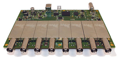
Most oscilloscopes are built down to a price. PicoScopes are built up to a specification. Careful front-end design and shielding reduces noise, crosstalk and harmonic distortion, meaning we are proud to publish the specifications for our scopes in detail. Decades of oscilloscope design experience can be seen in both improved pulse response and bandwidth flatness, and low distortion. The scope features 12 input ranges from ±10 mV to ±50 V full scale, a huge dynamic range, and 70 dB SFDR. The result is simple: when you probe a circuit, you can trust in the waveform you see on the screen. Digital triggeringMost digital oscilloscopes still use an analog trigger architecture based on comparators. This can cause time and amplitude errors that cannot always be calibrated out. The use of comparators often limits the trigger sensitivity at high bandwidths and can also create a long trigger re-arm delay. For over 20 years Pico have been pioneering the use of full digital triggering using the actual digitized data. This reduces trigger errors and allows our oscilloscopes to trigger on the smallest signals, even at the full bandwidth. All triggering is digital, resulting in high threshold resolution with programmable hysteresis and optimal waveform stability. The reduced re-arm delay provided by digital triggering, together with segmented memory, allows the capture of events that happen in rapid sequence. At the fastest timebase, rapid triggering can capture a new waveform every 3 microseconds until the buffer is full. The mask limit testing function helps to detect waveforms that fail to meet your specifications. Advanced triggers
As well as the standard range of triggers found on most oscilloscopes, the PicoScope 4824A has a comprehensive set of advanced triggers built in to help you capture the data you need. These include pulse width, windowed, and dropout triggers to help you find and capture your signal quickly. Hardware accelerationOn some oscilloscopes, enabling deep memory has a penalty: the screen update rate slows down and the controls become unresponsive as the processor struggles to cope with the amount of data. Thanks to the hardware acceleration inside PicoScope deep-memory oscilloscopes, you can collect waveforms containing hundreds of millions of samples while keeping fast screen update rates and a responsive user interface. 
Hardware acceleration ensures fast screen Dedicated hardware inside the oscilloscope processes multiple streams of data in parallel to construct the waveform that will be displayed on the screen. This is done far faster than any PC processor could manage, and together with USB 3.0 SuperSpeed data transfer eliminates any bottlenecks between the oscilloscope and the PC. For example, the scope may be set to capture 10,000,000 samples but the PicoScope display window may be only 1000 pixels wide. In this case, the scope intelligently compresses the data into 1000 blocks of 10,000 samples each. Unlike simple decimation, which throws away most of the data, PicoScope hardware acceleration guarantees that you see any high-frequency details such as narrow glitches, even when the display is zoomed out. Store up to 10,000 waveforms in the bufferEver spotted a glitch on a waveform, but by the time you’ve stopped the scope it has gone? With PicoScope you no longer need to worry about missing glitches or other transient events. Depending on the settings, PicoScope can store up to the last ten thousand waveforms in its buffer. More information on waveform buffer >>  Arbitrary waveform and function generators
The PicoScope 4824A has a built-in low-distortion, 80 MS/s, 14 bit arbitrary waveform generator (AWG), which can be used to emulate missing sensor signals during product development, or to stress test a design over the full intended operating range. Waveforms can be imported from data files or created and modified using the graphical AWG editor included. A function generator is also included, with sine, square, and triangle waves up to 1 MHz, along with DC level, white noise, and many more standard waveforms. As well as level, offset and frequency controls, advanced options allow you to sweep over a range of frequencies. Combined with the spectrum peak hold option, this creates a powerful tool for testing amplifier and filter responses. Spectrum analyzer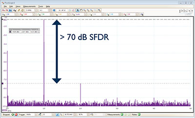
With the click of a button, you can open a new window to display a spectrum plot of selected channels up to the full bandwidth of the oscilloscope. A comprehensive range of settings gives you control over the number of spectrum bands, window types and display modes. A comprehensive set of automatic frequency-domain measurements can be added to the display, including THD, THD N, SINAD, SNR and IMD. You can even use the AWG and spectrum mode together to perform swept scalar network analysis. USB connectivity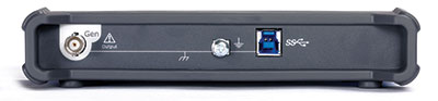
The SuperSpeed USB 3.0 connection not only allows high-speed data acquisition and transfer, but also makes printing, copying, saving, and emailing your data from the field quick and easy. USB powering removes the need to carry around a bulky external power supply, making the kit even more portable for the engineer on the move. The PicoScope 4824A is also backward compatible with older USB 2.0 devices. PicoScope performance and reliabilityWith over 20 years’ experience in the test and measurement industry, we know what’s important in an oscilloscope. The PicoScope 4824A delivers value for money by including a wide range of high-end features as standard. The PicoScope 6 software includes options such as serial decoding and mask limit testing, and new functionality is regularly delivered through free upgrades to ensure that your device does not quickly become outdated. All Pico Technology devices are optimized with the help of feedback from our customers. 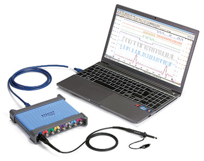
High-end features as standardBuying a PicoScope is not like making a purchase from other oscilloscope companies, where optional extras considerably increase the price. With our scopes, high-end features such as resolution enhancement, mask limit testing, serial decoding, advanced triggering, automatic measurements, math channels, XY mode, segmented memory, and a signal generator are all included in the price. To protect your investment, both the PC software and firmware inside the scope can be updated. Pico Technology have a long history of providing new features for free through software downloads. We deliver on our promises of future enhancements year after year, unlike many other companies in the field. Users of our products reward us by becoming lifelong customers and frequently recommending us to their colleagues. PicoScope Oscilloscope Software
PicoScope software is your complete test and measurement lab in one easy-to-use application.Start PicoScope software, click Auto setup and your PC is transformed into a powerful large-screen oscilloscope with the timebase and triggering already set up. Click Persistence mode for rapid screen updates with variable intensity for viewing complex analog signals or spotting digital glitches. Click Spectrum mode and your PC becomes an FFT spectrum analyzer. And there’s much more... 
Color persistence modesAdvanced display modes allow you to collect thousands of waveforms per second. New or more frequent data can be displayed in a brighter color or shade. This makes it easy to see glitches and dropouts and to estimate their relative frequency. Choose between analog persistence, digital color, or custom display modes. 
Mask limit testingPicoScope allows you to draw a mask around any signal with user-defined tolerances. This has been designed specifically for production and debugging environments, enabling you to compare signals. Simply capture a known good signal, draw a mask around it, and then attach the system under test. PicoScope will capture any intermittent glitches and can show a failure count and other statistics in the Measurements window. The numerical and graphical mask editors can be used separately or in combination, allowing you to enter accurate mask specifications, modify existing masks, and import and export masks as files. 
Serial decodingThe PicoScope 4824A includes serial decoding capability across all 8 channels as standard. The decoded data can be displayed in the format of your choice: In view, In window, or both at once.
PicoScope can also import a spreadsheet to decode the hexadecimal data into user-defined text strings. Currently PicoScope can decode I²C, RS-232/UART, SPI, I²S, FlexRay, LIN and CAN bus data. Expect this list to grow over time with future software upgrades. 
Automatic measurementsPicoScope allows you to automatically display a table of calculated measurements for troubleshooting and analysis. Using the built-in measurement statistics you can see the average, standard deviation, maximum and minimum of each measurement as well as the live value. You can add as many measurements as you need on each view. Each measurement includes statistical parameters showing its variability. 
Maths channelsWith PicoScope 6 you can perform a variety of mathematical calculations on your input signals and reference waveforms. Use the built-in list for simple functions such as addition and inversion, or open the equation editor and create complex functions involving trigonometry, exponentials, logarithms, statistics, integrals and derivatives. Zoom in and capture every last detail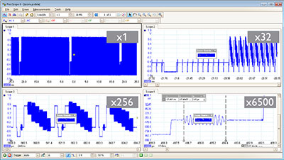
The PicoScope zoom function lets you take a closer look at the fine detail on your signals. Using simple point-and-click tools you can quickly zoom in on both axes and reveal every last detail of the signal, whilst the undo zoom function lets you return to the previous view. The image below shows four views of the same waveform, at x1, x32, x256, and x6500 zoom. Resolution enhancementResolution enhancement is a technique for increasing the effective vertical resolution of the scope at the expense of high–frequency detail. Selecting resolution enhancement does not change the scope’s sampling rate or the amount of data available. Resolution enhancement adds up to four bits to the effective resolution of your oscilloscope, so a PicoScope 4824A can deliver up to 16 bits. 
Custom probesThe custom probes feature allows you to correct for gain, attenuation, offsets and nonlinearities in special probes, or to convert to different units of measurement (such as current, power or temperature). You can save definitions to disk for later use. Definitions for standard Pico–supplied oscilloscope probes and current clampsare included. 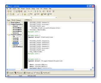
High-speed data acquisition and digitizingThe supplied drivers and software development kit allow you to both write your own software and interface to popular third-party software packages such as LabVIEW and MATLAB. The drivers support data streaming, a mode that captures gap-free continuous data over the USB port directly to the PC’s RAM or hard disk at up to 80 MS/s per channel (up to a total of 160 MS/s across all enabled channels) so you are not limited by the size of the scope’s buffer memory. Sampling rates in streaming mode are subject to PC specifications and application loading.
Documents
Specifications for the PicoScope 4824A 8-Channel Oscilloscopes
PicoScope 4824A 8 channel USB Oscilloscope Specifications
Note: quoted specifications apply when using PicoScope 6 software.
Order your 4824A Online at this link:
|
||||||||||||||||||||||||||||||||||||||||||||||||||||||||||||||||||||||||||||||||||||||||||||||||||||||||||||||||||||||||||||||||||||||||||||||||||||||||||||||||||||||||||||||||||||||||||||||||||||||||||||||||||||||||||||||||||||||||||||||||||||||||||||||||||||||||||||||||||||||||||||||||||||||||||||||||||||||||||||||||||||||||||||||||||||||||||||||||||||||||||||||||||||||||||||||||||||||||||||||||||||||||||||||||