


|
|
|||
| Log In | |||
|
| |||
|
| |||
| |||
| |||
| |||


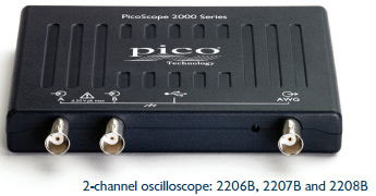
Picoscope 2200B Series 2 & 4 Channel Oscilloscopes
|
||||||||||||||||||||||||||||||||||||||||||||||||||||||||||||||||||||||||||||||||||||||||||||||||||||||||||||||||||||||||||||||||||||||||||||||||||||||||||||||||||||||||||||||||||||||||||||||||||||||||||||||||||||||||||||||||||||||||||||||||||||||||||||||||||||||||||||||||||||||||||||||||||||||||||||||||||||||||||||||||||||||||||||||||||||||||||||||||||||||||||||||||||||||||||||||||||||||||||||||||||||||||||||||||||||||||||||||||||||||||||||||||||||||||||||||||||||||||||||||||||||||||||||||||||||||||||||||||||||||||||||||||||||||||||||||||||||||||||||||||||||||||||||||||||||||||||||||||||||||||||||||||||||||||||||||||||||||||||||||||||||||||||||||||||||||||||||||||||||||||||||||||||||||

Advanced oscilloscope display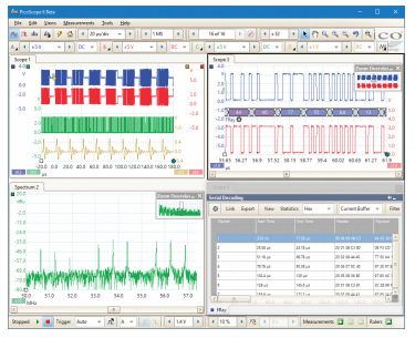 The PicoScope 6 software takes advantage of the display size and resolution and processing power of your PC – in this case displaying four analog signals, a zoomed view of two of the signals (undergoing serial decoding), and a spectrum view of a third, all at the same time. Unlike a conventional benchtop oscilloscope, the size of the display is limited only by the size of your computer monitor. The software is also easy to use on touch-screen devices – you can pinch to zoom and drag to scroll. |
  4channel.jpg) 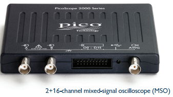 |
|
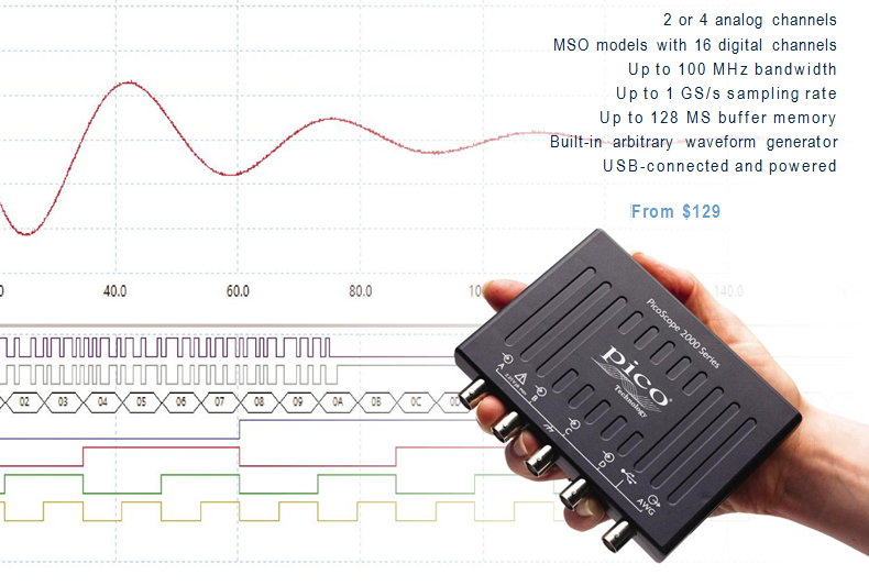
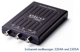
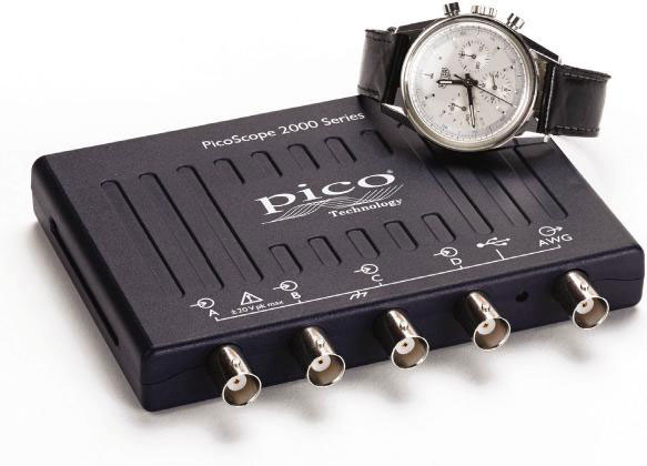
| Powerful, portable and super-small The PicoScope 2000 Series oscilloscopes are compact enough to fit easily into your laptop bag along with all their probes and leads. These modern alternatives to bulky benchtop devices are ideal for a wide range of applications including design, test, education, service, monitoring, fault-finding and repair and are perfect for engineers on the move. Fast sampling The PicoScope 2000 Series oscilloscopes provide fast real-time sampling rates of up to 1 GS/s on the analog channels: this represents a timing resolution of 1 ns. For repetitive analog signals, equivalent-time sampling (ETS) mode can boost the maximum effective sampling rate up to 10 GS/s, allowing even finer resolution down to 100 ps. All scopes support pre-trigger and post-trigger capture using the full memory depth. |
 |
|
 |
High signal integrityHere at Pico Technology, we’re proud of the dynamic performance of our products. Careful front-end design and shielding reduce noise, crosstalk and harmonic distortion. Decades of oscilloscope design experience can be seen in improved pulse response and bandwidth flatness.The result is simple: when you probe a circuit, you can trust in the waveform you see on the screen. |
|
High-end features as standardBuying a PicoScope is not like making a purchase from other oscilloscope companies, where increased functionality can considerably raise the price. PicoScopes are all-inclusive instruments, with no need for expensive upgrades to unlock the hardware. Other advanced features such as resolution enhancement, mask limit testing, serial decoding, advanced triggering, automatic measurements, math channels (including the ability to plot frequency and duty cycle against time), XY mode and segmented memory are all included in the price.
USB connectivityThe USB connection makes printing, copying, saving, and emailing your data from the field quick and easy. The high-speed USB interface allows fast data transfer, while USB powering removes the need to carry around a bulky external power supply.
FlexibilityThe PicoScope software offers a breadth of advanced features via a user-friendly interface. As well as the standard Windows installation, PicoScope Beta software also works effectively on Linux and Mac operating systems, giving you the freedom to choose which platform you operate your PicoScope from.
Unique commitment to product supportYour PicoScope gets better the longer you use it, thanks to the regular free updates we supply for both the PC software and the oscilloscope firmware throughout the life of the product: the performance and functionality of the scope both keep improving, without you paying a penny more than the purchase price.
This level of support, combined with the personal service provided by our technical and sales support teams, is reflected in the consistently good feedback we get from users of our products, many of whom have gone on to be regular customers.
|
||
PicoScope 2000 Specifications
Model |
PicoScope |
|||||||||
|---|---|---|---|---|---|---|---|---|---|---|
| Bandwidth | 10 MHz | 25 MHz | 50 MHz | 70 MHz | 100 MHz | |||||
| 2 channel | 2204A [PP906] | 2205A [PP907] | 2206B [PQ012] | 2207B [PQ013] | 2208B [PQ014] | |||||
| 4 channel | 2405A [PQ015] | 2406B [PQ016] | 2407B [PQ017] | 2408B [PQ018] | ||||||
| 2 channel MSO | 2205A MSO [PQ008] | 2206B MSO [PQ009] | 2207B MSO [PQ010] | 2208B MSO [PQ011] | ||||||
| Oscilloscope — vertical (analog inputs) | ||||||||||
| Bandwidth | 10 MHz | 25 MHz | 50 MHz | 70 MHz | 100 MHz | |||||
| Rise time (calculated) | 35 ns | 14 ns | 7 ns | 5 ns | 3.5 ns | |||||
| Vertical resolution | 8 bits | |||||||||
| Enhanced vertical resolution | Up to 12 bits | |||||||||
| Input ranges | ±50 mV, ±100 mV, ±200 mV, ±500 mV, ±1 V, ±2 V, ±5 V, ±10 V, ±20 V | ±20 mV, ±50 mV, ±100 mV, ±200 mV, ±500 mV, ±1 V, ±2 V, ±5 V, ±10 V, ±20 V | ||||||||
| Input sensitivity (10 vertical divisions) |
10 mV/div to 4 V/div | 4 mV/div to 4 V/div | ||||||||
| Input coupling | AC / DC | |||||||||
| Input connector | BNC(f) | |||||||||
| Input characteristics | 1 MΩ ± 1% ∥ 14 pF ± 2 pF | 1 MΩ ± 1% ∥ 16 pF ± 1 pF | ||||||||
| Analog offset range (vertical position adjustment) |
None | ±250 mV (20 mV to 200 mV ranges) ±2.5 V (500 mV to 2 V ranges) ±25 V (5 V to 20 V ranges) |
||||||||
| DC accuracy | ±3% of full scale ±200 μV | |||||||||
| Overvoltage protection | ±100 V (DC AC peak) | |||||||||
Oscilloscope — vertical (digital inputs, MSOs only) |
|
|---|---|
| Input channels | 16 channels (2 ports of 8 channels each) |
| Input connectors | 2.54 mm pitch, 10 x 2 way connector |
| Maximum input frequency | 100 MHz (200 Mb/s) |
| Minimum detectable pulse width | 5 ns |
| Input impedance (with TA136 cable) | 200 kΩ ±2% ∥ 8 pF ±2 pF |
| Input dynamic range | ±20 V |
| Digital threshold range | ±5 V |
| Overvoltage protection | ±50 V |
| Threshold grouping | Two independent threshold controls: Port 0: D0 to D7, Port 1: D8 to D15 |
| Threshold selection | TTL, CMOS, ECL, PECL, user-defined |
| Port threshold accuracy | ±350 mV (inclusive of hysteresis) |
| Hysteresis | < ±250 mV |
| Minimum input voltage swing | 500 mV pk-pk |
| Channel-to-channel skew | 2 ns typical |
| Minimum input slew rate | 10 V/µs |
Horizontal |
|||||||
|---|---|---|---|---|---|---|---|
| Maximum sampling rate (real-time)* | 100 MS/s | 200 MS/s | 500 MS/s | 1 GS/s | |||
| Equivalent sampling rate (ETS mode) | 2 GS/s | 4 GS/s | 5 GS/s | 10 GS/s | |||
| Maximum sampling rate (USB streaming) | 1 MS/s | 1 MS/s | 9.6 MS/s | ||||
| Shortest timebase | 10 ns/div | 5 ns/div | 2 ns/div | 1 ns/div | |||
| Longest timebase | 5000 s/div (approx 14 hours per waveform in chart recorder view) | ||||||
| Buffer memory (block mode)* | 8 kS | 16 kS | 48 kS | 32 MS | 64 MS | 128 MS | |
| Buffer memory (USB streaming mode) | 100 MS (shared between active channels) | ||||||
| Waveform buffers | 10 000 | ||||||
| Maximum waveforms per second | 2000 | 80 000 | |||||
| Timebase accuracy | ±100 ppm | ±50 ppm | |||||
| Sample jitter | 30 ps RMS typical | 3 ps RMS typical | |||||
Dynamic performance |
|||
|---|---|---|---|
| Crosstalk (full bandwidth, equal ranges) | Better than 200:1 | Better than 300:1 | |
| Harmonic distortion | < –50 dB at 100 kHz, full-scale input, typical | ||
| SFDR (100 kHz, full-scale input, typical) | > 52 dB | ±20 mV range: > 44 dB ±50 mV range and higher: > 52 dB |
|
| Noise | < 150 μV RMS (±50 mV range) |
< 220 μV RMS (±20 mV range) |
< 300 μV RMS (±20 mV range) |
| Bandwidth flatness | ( 0.3 dB, –3 dB) from DC to full bandwidth | ||
Triggering |
|||
|---|---|---|---|
| Sources | Ch A, Ch B, Ch C, Ch D. Any MSO digital channel | ||
| Trigger modes | None, auto, repeat, single | None, auto, repeat, single, rapid (segmented memory) | |
| Advanced triggers | Edge, window, pulse width, window pulse width, dropout, window dropout, interval, logic |
Edge, window, pulse width, window pulse width, dropout, window dropout, interval, runt pulse, logic |
|
| Trigger types, ETS | Rising or falling edge | Rising or falling edge (available on Ch A only) | |
| Trigger sensitivity, real-time | Digital triggering provides 1 LSB accuracy up to full bandwidth | ||
| Trigger sensitivity, ETS | 10 mV p-p, typical, at full bandwidth | ||
| Maximum pre-trigger capture | 100% of capture size | ||
| Maximum post-trigger delay | 4 billion samples | ||
| Trigger rearm time in rapid trigger mode | N/A | < 2 μs on fastest timebase |
< 1 μs on fastest timebase |
| Max. waveforms in rapid trigger mode | N/A | 96 | 10 000 |
Function generator |
||
|---|---|---|
| Standard output signals | Sine, square, triangle, DC voltage, ramp, sinc, Gaussian, half-sine | |
| Pseudorandom output signals | None | White noise, PRBS |
| Standard signal frequency | DC to 100 kHz | DC to 1 MHz |
| Sweep modes | Up, down, dual with selectable start/stop frequencies and increments | |
| Triggering | None | Free-run or up to 1 billion waveform cycles or frequency sweeps. Triggered from scope trigger or manually. |
| Output frequency accuracy | Oscilloscope timebase accuracy ± output frequency resolution | |
| Output frequency resolution | < 0.02 Hz | < 0.01 Hz |
| Output voltage range | ±2 V | |
| Output adjustments | Any amplitude and offset within ±2 V range | |
| Amplitude flatness (typical) | < 1 dB to 100 kHz | < 0.5 dB to 1 MHz |
| DC accuracy | ±1% of full scale | |
| SFDR (typical) | > 55 dB at 1 kHz full-scale sine wave | > 60 dB at 10 kHz full-scale sine wave |
| Output characteristics | Front panel BNC, 600 Ω output impedance | |
| Overvoltage protection | ±20 V | |
Arbitrary waveform generator |
|||
|---|---|---|---|
| Update rate | 1.548 MHz | 20 MHz | |
| Buffer size | 4 kS | 8 kS | 32 kS |
| Resolution | 12 bits | ||
| Bandwidth | > 100 kHz | > 1 MHz | |
| Rise time (10% to 90%) | < 2 μs | < 120 ns | |
Spectrum analyzer |
|
|---|---|
| Frequency range | DC to analog bandwidth of oscilloscope |
| Display modes | Magnitude, average, peak hold |
| Windowing functions | Rectangular, Gaussian, triangular, Blackman, Blackman-Harris, Hamming, Hann, flat-top |
| Number of FFT points | Selectable from 128 to half available buffer memory in powers of 2, up to a maximum of 1 048 576 points |
Math channels and Software filters |
|
|---|---|
| Functions | −x, x y, x−y, x*y, x/y, x^y, sqrt, exp, ln, log, abs, norm, sign, sin, cos, tan, arcsin, arccos, arctan, sinh, cosh, tanh, freq, derivative, integral, min, max, average, peak, delay, duty |
| Software filters | Highpass, lowpass, bandpass, bandstop |
| Operands | A, B (input channels), C, D (input channels, 4-channel models only), T (time), reference waveforms, constants, pi, digital channels (MSO models only) |
Automatic measurements |
|
|---|---|
| Scope mode | AC RMS, true RMS, frequency, cycle time, duty cycle, DC average, falling rate, rising rate, low pulse width, high pulse width, fall time, rise time, minimum, maximum, peak to peak |
| Spectrum mode | Frequency at peak, amplitude at peak, THD dB, SNR, SINAD, SFDR, total power, average amplitude at peak, THD %, THD N, IMD |
| Statistics | Minimum, maximum, average and standard deviation |
Serial decoding |
|
|---|---|
| Protocols | 1-Wire, ARINC 429, CAN, DCC, DMX512, FlexRay, Ethernet 10Base-T, USB 1.1, I²C, I²S, LIN, PS/2, SPI, SENT, UART/RS-232 (subject to bandwidth and sampling rate of chosen oscilloscope model) |
| Mask limit testing | |
|---|---|
| Mask generation | Numeric (automatic) or Graphical (manual) |
| Statistics | Pass/fail, failure count, total count |
| Available actions on mask fail | Beep, play sound, stop capture, save waveform, trigger signal generator / AWG, run executable |
Display |
|
|---|---|
| Interpolation | Linear or sin(x)/x |
| Persistence modes | Digital color, analog intensity, custom, fast or none |
SDK / API details and specifications for customers writing their own software |
|||||
|---|---|---|---|---|---|
| Supplied drivers | 32 and 64-bit drivers for Windows 7, 8 and 10 Linux drivers Mac OS X drivers |
||||
| Example code | C, C#, Excel VBA, VB.NET, LabVIEW, MATLAB | ||||
| Maximum USB streaming sampling rate* | 1 MS/s | 5 MS/s | 31 MS/s | ||
| Buffer memory in USB streaming mode* | Limited only by PC | ||||
| Segmented memory buffers* | N/A | 96 | 128000 | 256000 | 512000 |
General |
||
|---|---|---|
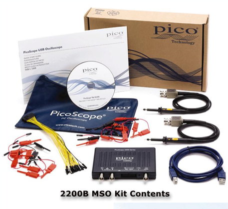
| Package contents | PicoScope 2000 series oscilloscope 2 or 4 switchable 10:1/1:1 oscilloscope probes (except for PicoScope 2204A / 2205A when purchased without probes) TA136 digital cable (MSOs only) 2 × TA139 pack of 10 logic test clips (MSOs only) USB cable Software and reference CD Quick start guide |
|
| PC connectivity | USB 2.0 (USB 3.0/3.1 compatible). | |
| Power requirements | Powered from USB port | |
| Dimensions (including connectors and feet) |
142 x 92 x 18.8 mm | 130 x 104 x 18.8 mm |
| Weight | < 0.2 kg (7 oz) | |
| Temperature range, operating | 0 °C to 50 °C | |
| Temperature range, operating, for stated accuracy |
15 °C to 30 °C | |
| Temperature range, storage | –20 °C to 60 °C | |
| Humidity range, operating | 5% to 80% RH non-condensing | |
| Humidity range, storage | 5% to 95% RH non-condensing | |
| Altitude range | up to 2000 m | |
| Pollution degree | 2 | |
| Safety approvals | Designed to EN 61010-1:2010 | |
| Environmental approvals | RoHS, WEEE | |
| EMC approvals | Tested to meet EN61326-1:2013 and FCC Part 15 Subpart B | |
| Software included | PicoScope 6 for Microsoft Windows 7, 8 and 10 32-bit and 64-bit SDK for Windows 7, 8 and 10 32-bit and 64-bit example programs (C, Microsoft Excel VBA, LabVIEW) |
|
| Free software available for download | PicoScope 6 (beta) for Linux and OS X. Please note that the Linux and OS X beta versions of PicoScope do not yet have mask limit test or math channel functions. SDK (beta) for Linux and OS X |
|
| Languages supported | Simplified Chinese, Czech, Danish, Dutch, English, Finnish, French, German, Greek, Hungarian, Italian, Japanese, Korean, Norwegian, Polish, Portuguese, Romanian, Russian, Spanish, Swedish, Turkish | |
Link to PicoScope Software Downloads
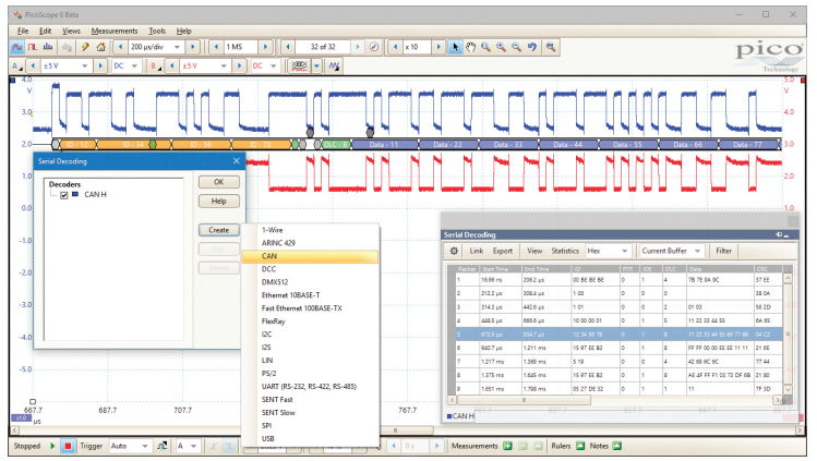
Serial decoding
• Graph format shows the decoded data beneath the waveform on a common time axis, with error frames marked in red. You can zoom in on these frames to investigate noise or distortion. The data packets are broken down into their component fields, making it easier than ever to locate and identify problems signals, and each packet field is assigned a different color: in the CAN bus example below, the address is colored orange, the DLC green and the data content indigo. Color coding is available in PicoScope 6.12 or later, available for download from www.picotech.com.
• Table format shows a list of the decoded frames, including the data and all flags and identifiers. You can set up filtering conditions to display only the frames you are interested in, search for frames with specified properties, or define a start pattern to signal when the program should list the data.
It is also possible to link decoded numeric data to user-defined text strings, for ease of reading.
With the PicoScope 2000 Series, you can decode up to 15 serial protocols, including 1-Wire, CAN, I2 C, I2 S, LIN, SENT, SPI and UART/RS- 232, depending on the bandwidth and sampling rate of the oscilloscope model. Please see the specification table for the full list.
PicoScope also includes options to import and export the decoded data using a Microsoft Excel spreadsheet.
Serial decoding for digital signals
More PicoScope 6 Software details ->
PicoScope 2000 Series Educational Brochure ->
Order:
Package Contents Include the Following:
|
2200A & B (2Channel, 4 Channel Plus MSO's) Oscilloscopes: |
||
| ORDER CODE | DESCRIPTION | |
| PP917 | PicoScope 2204A 10 MHz 2-channel oscilloscope without probes | |
| PP906 | PicoScope 2204A 10 MHz 2-channel oscilloscope | |
| PP966 | PicoScope 2205A 25 MHz 2-channel oscilloscope without probes | |
| PP907 | PicoScope 2205A 25 MHz 2-channel oscilloscope | |
| PQ012 | PicoScope 2206B 50 MHz 2-channel oscilloscope | |
| PQ013 | PicoScope 2207B 70 MHz 2-channel oscilloscope | |
| PQ014 | PicoScope 2208B 100 MHz 2-channel oscilloscope | |
| PQ015 | PicoScope 2405A 25 MHz 4-channel oscilloscope | |
| PQ016 | PicoScope 2406B 50 MHz 4-channel oscilloscope | |
| PQ017 | PicoScope 2407B 70 MHz 4-channel oscilloscope | |
| PQ018 | PicoScope 2408B 100 MHz 4-channel oscilloscope | |
| PQ008 | PicoScope 2205A MSO 25 MHz 2 16 channel mixed-signal oscilloscope | |
| PQ009 | PicoScope 2206B MSO 50 MHz 2 16 channel mixed-signal oscilloscope | |
| PQ010 | PicoScope 2207B MSO 70 MHz 2 16 channel mixed-signal oscilloscope | |
| PQ011 | PicoScope 2208B MSO 100 MHz 2 16 channel mixed-signal oscilloscope | |
Replacement Accessories: |
||
| ORDER CODE | DESCRIPTION | |
| MI007 | 60 MHz passive probe (supplied in oscilloscope kits with up to 50 MHz bandwidth) |
|
| TA132 | 150 MHz passive probe (supplied with 70 MHz and 100 MHz oscilloscopes) |
|
| TA136 | 20-way 25 cm digital cable (suitable for MSOs only) | |
| TA139 | Pack of 10 logic test clips (suitable for MSOs only) | |