Log In

Celebrating 45 Years

Follow us on Facebook for all the latest news, updates and promotions


Credit Cards Accepted


Aurora Probability in Northern Canada

Auroral forecast from AuroraWatch.ca


North America Aurora Map from
NOAA Space Weather Prediction Center

Aurora Map - NOAA


RIOD24

 
acces i/o logo
  US Pricelist
CND Pricelist
Privacy and Security Policy 


24-Bit Digital I/O Pod

Features

  • Intelligent Distributed Digital I/O
  • Opto-Isolated RS-485 Serial Interface to Host Computer
  • 24-Bits of Bit, Byte, and 24-bit Word Programmable I/O
  • Open Collector Digital Outputs for Sinking Up To 350mA
  • 50 Volt DC Compatible Digital Inputs and Outputs
  • 16-Bit Digital Input Event Counter on Every Input
  • Digital Outputs May Be Either Level or Pulse
  • Change-of-State Detection for Low-Latency Contact Monitoring
  • All Programming In Software, No Switches or Jumpers to Set
  • NEMA4 Enclosure for Harsh Atmospheric or Marine Environments
  • 8031-Compatible Microcontroller with 8K of EEPROM and SRAM (32K optional)


Remote ACCES Distributed I/O Pods provide intelligent sensor interfaces via two-wire RS-485 multidrop networks to host PCs.  Model RIOD24 is ACCES' answer to Distributed Digital I/O needs.  With these Pods you can connect 2 wires to any computer and be quickly controlling and acquiring your digital signals. RS-485 supports very long cable lengths (up to 4000 feet) and with our Wireless option you can achieve over 10 milesbetween devices.

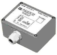
The RIOD24 comes standard in a NEMA4 enclosure provided excellent protection from the elements, indoors or out.  The closable gasket aperture forms a perfect seal around your round cable, and our conductive lid-gasket and solid aluminum box prevent EMI emmisions for those noisy factory floor environments.

Digital Inputs may be read individually, in 8-bit bytes, or in 24-bit words at voltages up to 50 VDC. There are also digital software counters on each input. Selectable edges can be counted for up to 65,535 transitions. These counters support Read and Reset commands. Moreover, change-of-state flags can be set on any enabled input bits and can be read via the serial port. This is particularly useful in applications where it is necessary to detect contact closures or openings. This change-of-state detection capability is enabled on a bit-by-bit basis for all bits that are programmed to be inputs. Digital-input sample rate is software programmable from 14 Hz to 1 KHz.

Digital Outputs may be programmed individually, in 8-bit bytes, or in 24-bit words. These outputs may be latched, pulsed, or set to free run at a programmed rate. The digital output drivers are open-collector circuits that have 350 mA drive capability at a logic "low". RIOD24 outputs can comply with up to 50 VDC (voltage supplied by you) or, if no external voltage is available, outputs will be pulled up by an internal 10 kilohm resistor to 5 VDC. The digital-output square wave pulse rate is software programmable from 7 Hz to 500 Hz.

A built-in watchdog timer resets the pod if for some unexpected reason the microcontroller "hangs up" or if the power supply voltage drops below 4.75 VDC. Also, data collected by the pod are stored in local RAM for later access through the computer's serial port. This feature facilitates a stand-alone mode of operation. For example, a notebook computer can connect to the RS-485 network and collect the data.

UTILITY SOFTWARE

ACCES provides ASCII-based software with the pod on CD. ASCII programming permits you to write applications in any high level language that supports ASCII string functions and you can use these and other REMOTE ACCES Series modules with virtually any computer. The communication protocol has two forms: non-addressed and addressed. You use non-addressed protocol if only one pod is in use. If more than one pod is in use, then you use addressed protocol. In addressed mode, an address command is sent to enable communication with the specific pod. That address command needs to be sent only once to enable communication with that specific pod and disables communications with all other pods on the network until a different address command is issued.

Samples are provided in DOS and Windows languages, including Turbo Pascal, Borland C/C , C Builder, Delphi, VisualBASIC and VisualC .  These samples can be easily modified into real-world applications by anyone with passing familiarity with any programming language, as our source-code-provided "drivers" vastly simplify serial-port programming as needed for our Pods.

The command structure is seven data bits, even parity, one stop bit. All numbers sent to and received from the pod are in hexadecimal form. Commands are issued in simple, easy-to-learn letter and number combinations. Here are some examples:

MLxx(Enter)
configures bits 00 through 07
[0 = input and 1 = output]

I(Enter)
commands reading of
all 24 digital bits

O01 (Enter)
commands a low output
on bit 01

I/O CONNECTIONS

Input/Output connections are made at a screw terminal assembly inside the top cover of the pod. Terminal assignments are listed on the label on the cover of the pod. A sealing gland is included for full NEMA compliance.

Specifications


Digital Inputs

  • Number: Up to 24. Can be programmed, on a bit-by-bit basis, on an 8-bit byte basis, or on a 24-bit word basis. In this latter case, there would be no capability for digital outputs.
  • Sample Rate: Programmable from 14 Hz to 1 KHz.
  • Software Counters: There are 16-bit software counters on all bits programmed to be inputs. These can be programmed to increment on either rising or falling edges.
  • Change of State Detection: Change-of-state flags can be set on any enabled input bits and can be read via the serial port.
  • Logic Input Low: -0.5V to 0.8V.
  • Logic Input High: 2.0V to 50.0V
  • Low-level Input Current: 450 microampere maximum.

Digital Outputs

  • Number: Up to 24. Can be programmed, on a bit-by-bit basis, on an 8-bit byte basis, or on a 24-bit word basis. In this latter case, there would be no capability for digital inputs.
  • Type: Outputs can be latched, pulsed, or set to free-run for a prescribed period of time.
    Pulsed outputs are square wave and programmable from 7 Hz to 500 Hz.
  • Logic-Low Ouput Current: 350 mA maximum. (See box below.) Inductive suppression diode included in each circuit.
Maximum allowable current per output bit is 350 mA but, for each six-bit group there is a cumulative maximum total of 650 mA. Output groups are bits 0-5, 6-11, 12-17, and 18-23 (decimal).
  • High-Level Output Voltage: Open Collector, Up to 50VDC compliance. If no user-supplied voltage, outputs are pulled up to 5 VDC via 10K resistors.

Environmental

  • Operating Temperature Range: 0o to 65oC (Optional -40o to 80oC.). See Temperature De-rating discussion on the REMOTE ACCES Overview page that presents "Specifications Common to all REMOTE ACCES Pods" for temperature de-rating based on power voltage applied.
  • Storage Temperature Range: -50o to 120oC.
  • Humidity: 5% to 95% non-condensing. Enclosure is designed to meet NEMA4 requirements.
  • Size: NEMA4 enclosure 4.53" long by 3.54" wide by 2.17" high.(115mm x 90mm x 55mm)

Power Required

Power for the opto-isolated section can be applied from the computer's 12 VDC power supply via the serial communication cable. Power for the rest of the pod can be supplied by a local power supply.
  • Opto-Isolated Section: 7.5 to 25 VDC @ 40 mA. (Note: Due to the small amount of current required, voltage drop in the communication cable will be inconsequential.)
  • Local Power: 7.5 to 16 VDC @ 150 mA. See box below if local power is greater than 16VOC:
If the local power supply has an output voltage greater than 16VDC, you can install a zener diode in series with the supply voltage. The voltage rating of the zener diode (VZ) should be equal to VI - 16 where VIis the power supply voltage. The voltage rating of the zener diode should be VZ x 0.15 watts. Thus, for example, a 24 VDC power supply would require use of an 8.2V zener diode with a power rating of 8.2 x 0.15 equals approx. 1 watt.


Regulatory Compliance
Declaration of Conformity, and Test Reports are on file. Users must use appropriate shielded cables.
Acquisition Control Communications Engineering / Systems


USA Office

Tel:1.877.902.2979-1.425.223.4311
Fax:1.877.329.4324
Address: 1480 Gulf Road, Suite 837,
PO Box 1364
Point Roberts, WA 98281

Western Canada - Vancouver BC

Tel:1.800.663.6001 or 1.604.925.6150
Fax:1.604.925.6170
Address: 2454 Haywood Ave
West Vancouver, BC V7V 1Y1

Eastern Canada - Markham, Ontario

Tel:1.800.465.0164 or 1.905.513.7027
Fax:1.877.329.4324