Log In

Celebrating 45 Years

Follow us on Facebook for all the latest news, updates and promotions


Credit Cards Accepted


Aurora Probability in Northern Canada

Auroral forecast from AuroraWatch.ca


North America Aurora Map from
NOAA Space Weather Prediction Center

Aurora Map - NOAA


RDG-24

 acces i/o logo
   US Pricelist
CND Pricelist
Privacy and Security Policy


REMOTE ACCES 24-bit Digital I/O Card

Features

 
  • Remote Intelligent Digital I/O
  • Opto-Isolated RS-485 Serial Interface to Host Computer
  • 24-Bit Digital I/O Programmable Bit-by-Bit, in 8-Bit Bytes, or in 24-Bit Words
  • Digital Input and Output Voltages up to 50VDC
  • Open Collector Digital Outputs for Loads up to 350mA
  • Protective Steel Enclosure
  • Type 8031 Microcontroller with 8K x 8 RAM and 8K x 8 EEPROM (32K x 8 optional)
  • All Programming in Software, No Switches to Set. Jumper to Set 2-Wire or 4-Wire modes, and Jumpers (3) to By-Pass Opto-Isolators if Desired.
  • 16-Bit Digital-Input Software Counters
  • Change of State Flag Readable via the Serial Port
  • Digital Outputs May Be Either Level or Pulse.
 
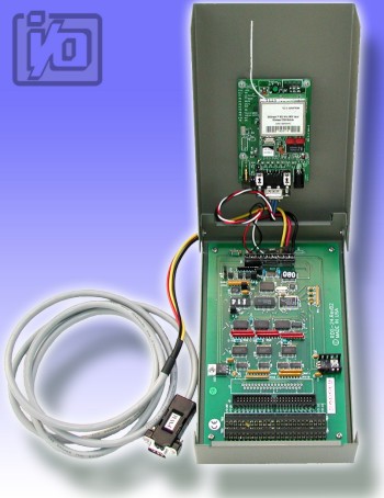
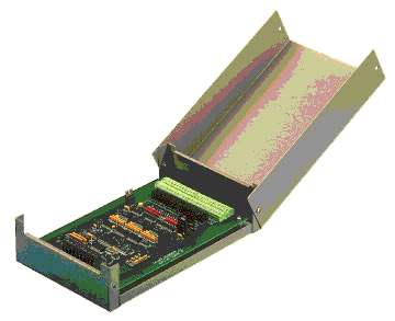
Model RDG-24 is an intelligent, 24-bit parallel digital-I/O-to-computer interface unit. RDG-24 is enclosed in a steel enclosure for use in hostile environments. There are no switches or jumpers to set to enable half-duplex operation. In RDG-24 there are jumpers to bypass the opto-isolators if you wish, plus there are jumpers to set full-duplex operation if you desire.

Digital Inputs may be read individually, in 8-bit bytes, or in 24-bit words at voltages up to 50 VDC. There are also digital software counters on each input. Selectable edges can be counted for up to 65,535 transitions. These counters support Read and Reset commands. Moreover, change-of-state flags can be set on any enabled input bits and can be read via the serial port. This is particularly useful in applications where it is necessary to detect contact closures or openings. This change-of-state detection capability is enabled on a bit-by-bit basis for all bits that are programmed to be inputs. Digital-input sample rate is software programmable from 14 Hz to 1 KHz.

Digital Outputs may be programmed individually, in 8-bit bytes, or in 24-bit words. These outputs may be latched, pulsed, or set to free run at a programmed rate. The digital output drivers are open-collector circuits that have 350 mA drive capability at a logic "low". RDG-24 outputs can comply with up to 50 VDC (voltage supplied by you) or, if no external voltage is available, outputs will be pulled up by an internal 10 Kilohm resistor to 5 VDC. The digital-output square wave pulse rate is software programmable from 7 Hz to 500 Hz. A built-in watchdog timer resets the pod if, for some unexpected reason the microcontroller "hangs up" or if the power supply voltage drops below 4.75 VDC. Also, data collected by the pod are stored in local RAM for later access through the computer's serial port. This feature facilitates a stand-alone mode of operation. For example, a portable or laptop computer that has an RS-485 port can be brought to the pod, connected, and collect the data.

Specifications

Digital Inputs

  • Number: Up to 24. Can be programmed, on a bit-by-bit basis, on an 8-bit byte basis, or on a 24-bit word basis. In this latter case, there would be no capability for digital outputs.
  • Sample Rate: Programmable from 14 Hz to 1 KHz.
  • Software Counters: There are 16-bit software counters on all bits programmed to be inputs. These can be programmed to increment on either rising or falling edges.
  • Change of State Detection: Change-of-state flags can be set on any enabled input bits and can be read via the serial port.
  • Logic Input Low: -0.5V to 0.8V.
  • Logic Input High: 2.0V to 50.0V
  • Low-level Input Current: 450 microampere maximum.

Digital Outputs

  • Number: Up to 24. Can be programmed, on a bit-by-bit basis, on an 8-bit byte basis, or on a 24-bit word basis. In this latter case, there would be no capability for digital inputs.
  • Type: Outputs can be latched, pulsed, or set to free-run for a prescribed period of time.
    Pulsed outputs are square wave and programmable from 7 Hz to 500 Hz.
  • Logic-Low Ouput Current: 350 mA maximum. (See box below.) Inductive suppression diode included in each circuit.
Maximum allowable current per output bit is 350 mA but, for each six-bit group there is a cumulative maximum total of 650 mA. Output groups are bits 0-5, 6-11, 12-17, and 18-23 (decimal).
  • High-Level Output Voltage: Open Collector, Up to 50VDC compliance. If no user-supplied voltage, outputs are pulled up to 5 VDC via 10K resistors.

Environmental

  • Operating Temperature Range: 0o to 65oC (Optional -40o to 80oC.). See Temperature De-rating discussion on the REMOTE ACCES Overview page that presents "Specifications Common to all REMOTE ACCES Pods" for temperature de-rating based on power voltage applied.
  • Storage Temperature Range: -50o to 120oC.
  • Humidity: 5% to 95% non-condensing. Enclosure is designed to meet NEMA4 requirements.

Power Required

Power for the opto-isolated section can be applied from the computer's 12 VDC power supply via the serial communication cable. Power for the rest of the pod can be supplied by a local power supply.
  • Opto-Isolated Section: 7.5 to 25 VDC @ 40 mA. (Note: Due to the small amount of current required, voltage drop in the communication cable will be inconsequential.)
  • Local Power: 7.5 to 16 VDC @ 150 mA. See box below if local power is greater than 16VOC:
If the local power supply has an output voltage greater than 16VDC, you can install a zener diode in series with the supply voltage. The voltage rating of the zener diode (VZ) should be equal to VI - 16 where VIis the power supply voltage. The voltage rating of the zener diode should be VZ x 0.15 watts. Thus, for example, a 24 VDC power supply would require use of an 8.2V zener diode with a power rating of 8.2 x 0.15 equals approx. 1 watt.


Part Number Price(USD)
RDG-24 call us
WM-RDG-24  
U-RDG-24  
S-RDG-24  
E-RDG-24  
View / Download Manual (in .pdf format)
Acquisition Control Communications Engineering / Systems


USA Office

Tel:1.877.902.2979-1.425.223.4311
Fax:1.877.329.4324
Address: 1480 Gulf Road, Suite 837,
PO Box 1364
Point Roberts, WA 98281

Western Canada - Vancouver BC

Tel:1.800.663.6001 or 1.604.925.6150
Fax:1.604.925.6170
Address: 2454 Haywood Ave
West Vancouver, BC V7V 1Y1

Eastern Canada - Markham, Ontario

Tel:1.800.465.0164 or 1.905.513.7027
Fax:1.877.329.4324