|
|
||||
| Log In | ||||
|
| ||||
| ||||
| ||||
| ||||
| ||||
| ||||
| ||||
| ||||


|
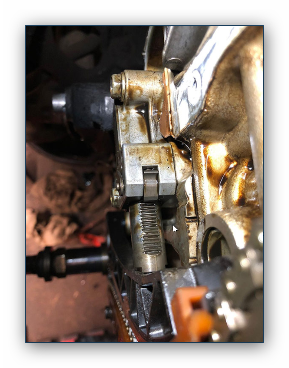
This is another favourite complaint: Fiat Punto 1.2L ECM failure. The car suddenly developed a misfire and never recovered. It was driven to the customer's own local garage, where they carried out the usual checks, and was starting to look like the ECM had failed. As someone who discourages the practice of diagnosing a car from reading a job card, even I took an "expected" approach to this one, as I had been called in to simply confirm the fault. The garage had ticked all the boxes for external checks, and had carried out a good elimination process leaving the ECM as a suspect. The next step was to hook up the scope and prove the fault. Tests so far had isolated the problem to a poor spark on cylinders 2 and 3, so the focus of the investigation turned to their coil and its primary signal. 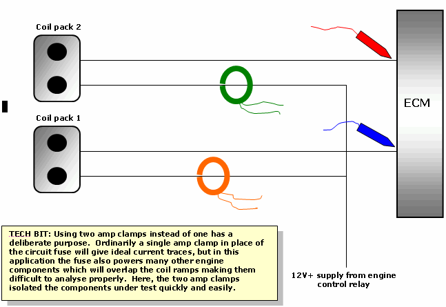 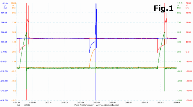 
Fig.1 was a typical capture recorded at idle and with the engine misfiring. You can see that the current peaks are very different: our good primary circuit (coil 2) is consuming 5.5 A unsaturated and our suspect primary circuit (coil 1) is consuming only 3 A unsaturated. It follows that the magnetic energy accumulated in coil 1 will be weak and when the primary field collapses there will be little kV induced and available to sustain a healthy spark line - you get out what you put in. To prove the case, notice the difference in spark burn times: coil 1 about 0.4 ms and coil 2 about 1.2 ms. This is essentially the reason for the misfire: our coil is not collecting a good primary charge. We've determined that our circuit current is low, so by applying Ohm's Law we must either have a high circuit resistance or a low voltage supply. Firstly we'll address the possibility of a high circuit resistance. 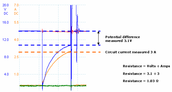
Like many other ignition controllers, this ECM regulates the ground supply to obtain a safe working current and deliver plenty of energy to the primary. Whenever the coil current is increasing, the coil creates a self-induced voltage or "back-EMF" in the opposite direction which briefly opposes and restricts current flow. In reality, these measurements are taken while the coil is still charging, so this back-EMF is contributing to the calculation. However, in this example, you can see the charge ramp tailing off and approaching a saturated state, so any remaining back-EMF will not significantly alter the result of this exercise. With a calculated circuit resistance of about 1 Ω (and still dropping as self-induction diminishes) this is not contributing to the fault, which leaves voltage difference supplied to the load (the coil) as the likely problem. First, the 12 V supply at the coil was manually verified as good and eliminated. Here I recorded 3.1 V potential difference just before the primary pulse ended. We can compare this electrical characteristic to the known good primary of coil 2 and see what the differences are. 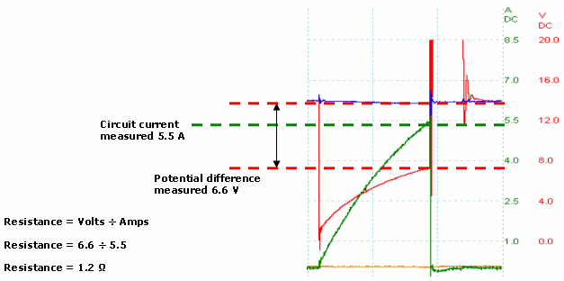
As expected, this is much better. The key difference is the ECM delivering a lower ground level to the primary circuit which has increased total voltage available, over double that of coil 1. This in turn has increased the current through the primary windings and created a strong magnetic field ready to be collapsed. Here the circuit resistance was calculated at 1.2 Ω before the primary pulse released, so back-EMF is having a greater effect on this calculation as the charge angle is relatively steep. We expect the true circuit resistance to be lower than 1.2 Ω. The fault is confirmed as a poor ground level emitted by the ECM. Note the voltage probe hook-up points at the beginning. By taking measurements of the switched ground close to the source, we further localised the problem to the engine controller or its own ground path. This ECM receives a ground from its own casing via a bolted-on ground lead. Quite simply, if one coil driver circuit is providing a good primary pulse then so should the other; so the fault is internal to the ECM. In the overlay image, did you notice the sudden ground hike in the coil 1 primary pulse? Renewing the coils, leads and plugs is a good investment against repeat failure of the new ECM.
|
||||||