Features:
-fast rise time (5-20 ns depending on R value)
-coaxial current path
-variable resistance (typical 100 milli Ohm to 50 Ohm for transformer testing and up to 50k Ohm for leakage current measurements) achieved by various combinations of lumped-elements, non-inductively wound resistors.
-internal compensation.
Applications:
-indoor use for laboratories and manufacturing facilities
-measurement of winding currents during the impulse testing of power and distribution transformers, instrument transformers (VT's), reactors etc.
-measurement of a capacitive coupling currents when conducting LVI (low-voltage impulse) tests on transformers
-measurement of leakage currents (AC & DC) when testing insulators, bucket truck booms,surge arresters etc.

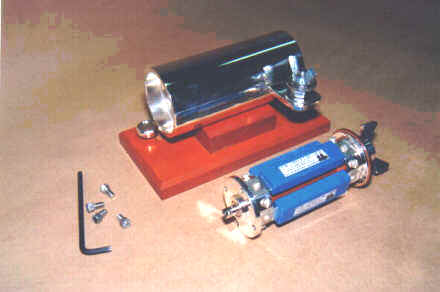
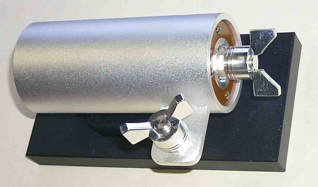
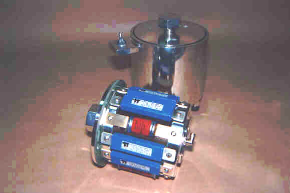
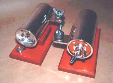
Design:
The shunt is of a coaxial design (cylindrical shape) using exchangeable resistive elements in a robust body. Variable resistance is achieved by using several elements of the same or different ohmic value connected in parallel. The shunt body and resistive element terminals are silver plated for good contact. The shunt is internally compensated for better response. The shunt output is through a coaxial cable connector of the customer's choice (BNC, LEMO, RF, etc.)
Two models are available:
| Elements in Parallel |
Diameter |
Length |
Weight |
| Model A |
Up to 12 |
170mm |
205mm |
12.5kg |
| Model B |
Up to 4 |
75mm |
205mm |
3.7kg |
The Model A shunt design also offers the possibility of connecting one to several capacitors in parallel with the resistive elements to suppress the capacitive component of the current waveform (appearing during the first few microseconds when testing high voltage windings). Recommended capacitors (rated 2KVDC) are 0.5 uF (quantity 3) and 0.1uF (quantity 2). (This option is not available with the Model B design)