|
The vehicle
The problem
This Chrysler Concord (coil over plug system) came in with a cylinder–specific misfire problem. With some testing I found that the number 5 coil had no spark.
The investigation
Note: The amp clamp was set to 100 mv/amp and I am using a voltage scale instead of current.
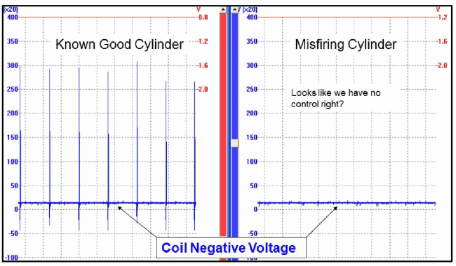
The first capture (Figure 1) shows the number 5 coil (right picture) voltage waveform compared to a known good firing cylinder (left picture).
Figure 1
As with any ignition coil with no spark, one of the first tests is to determine if the coil has “control” or not. This can be done with a test light as in the video below or with a scope, watching either coil negative voltage or coil primary current. So again, in the above picture I have chosen to perform a voltage waveform first of the coil negative circuit. As illustrated in the misfiring cylinder, it looks like there is no “control” (coil negative is not being switched on/off to ground/earth).
Video........
As far as my time base setting is concerned, when I am doing initial “control” testing I am not concerned with detail as much as I am repetition. This is the reason for this longer (less detailed) time base. We will change that later.
This second capture changes things a bit.
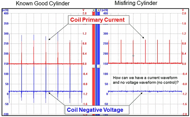
Figure 2
As you can see in Figure 2, there is control on the primary circuit as indicated by current flow pulses. So how can there be current flow and no voltage drop? It’s time to zoom in on these captures.
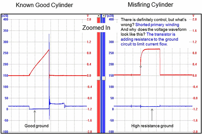
Figure 3
Notice that in the known good cylinder the transistor is applying a full ground as noted by the near 0 volts during the on–time (dwell) of the ignition coil. Also in the known good cylinder you see a nice ramp effect with the current waveform. This is due to counter electromotive force or counter voltage that is being generated by an expanding magnetic field around a coil of wire. If you recall, when there is motion, a magnetic field and a conductor, voltage can be created in the conductor. The motion is the expanding magnetic field of the primary winding. The conductor is the primary winding itself and the magnetic field is, of course, from an electro magnet. To simplify this, we can say that the voltage and current passing through the coil primary windings is generating a second “counter” voltage. This counter voltage opposes the incoming current flow and creates a ramp effect.
In the misfiring cylinder you will notice that the transistor is not applying a full ground to this coil. This is noted by the high voltage during the on–time (dwell) of the ignition coil. There is also no large voltage spike at the end of the dwell time. This is because there is no magnetic field being generated from the shorted winding, so there is nothing to collapse. Also you can see in the current waveform that there is no ramp and there is a straight up line in current flow.
We need to zoom in one more time on the misfiring cylinder coil.
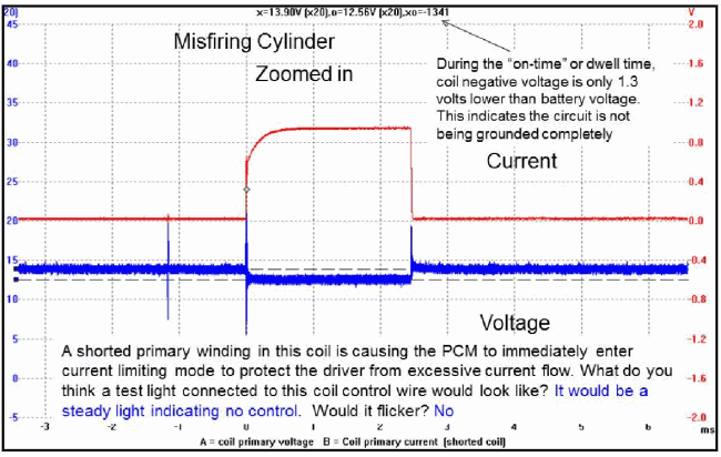
Figure 4
So as noted in Figure 4 the transistor is indeed switching on/off to ground (there is “control”). The missing ramp in the current waveform is due to a shorted coil primary winding. If the winding is shorted it will not generate a magnetic field. So there will be no counter voltage or no opposition to current flow (no resistance). This causes a major increase in current and no ramp effect. The transistor must limit the current flow to protect itself from “burning up”. This is why our coil negative voltage shows high voltage during the on–time (dwell) of the waveform.
In conclusion we must remember this variable when testing for no spark on ignition coils. If the primary winding is shorted it can seem as if there is “no control” especially if we don’t set up our voltage and time bases correctly. This would lead us away from the coil and toward the module or computer and, of course, a costly misdiagnosis. Also if you decided to use a test light on coil negative as a quick test for “control”, the test light will not flicker. This would cause the same misdiagnosis.
|