|
We know that intermittent faults are the bane of our lives in the garage and often a fault can happen before your eyes, but might pass without a chance to spot the glitch on your scan-tool or to take a measurement with your multimeter. Even an oscilloscope can miss a glitch, so it is important to use a setup that is most likely to capture the moment a problem occurs.
Recently though we were fortunate to have the scope set up whilst a problematic Peugeot faltered before our eyes, thankfully the scope was gathering data. This Peugeot 406 2.0 HDI (code RHY Bosch system) was reported to be randomly losing power and bringing on the MIL (Malfunction Indicator Lamp). We initially started off by plugging the scan-tool in and noting the following fault codes:
P0191 Fuel rail pressure signal coherence.
P1138 Fuel pressure control solenoid circuit range/performance.
Hmm... where to start?
There is no simple answer here and your approach will probably depend on the ease of access to the associated components. A physical injector leak off test might be a first step, but on the other hand if the injectors are buried deep and the rail pressure sensor is easier to access then that might be the focus of your efforts. In our case as a "solenoid circuit issue" is mentioned, it was felt that that the high pressure fuel regulator control should be studied in greater detail.
It is worth taking a moment to consider the various ways that we can evaluate things with a modern oscilloscope and I use the word "modern" with good reason. Historically the technician has been restricted to some degree when using a scope, by the limitations of sample rate over longer time bases, which would mean that the finer detail needed for close scrutiny would be lost. In the past, the best way of capturing fast events, would be with a short collection time and this would have been considered an adequate method. These days though we are spoiled somewhat with the immense detail that Picoscope can capture, for the past few years we have had the opportunity to capture impressive detail, with massive amounts of screen time in comparison to older models and the majority of alternative automotive scopes.
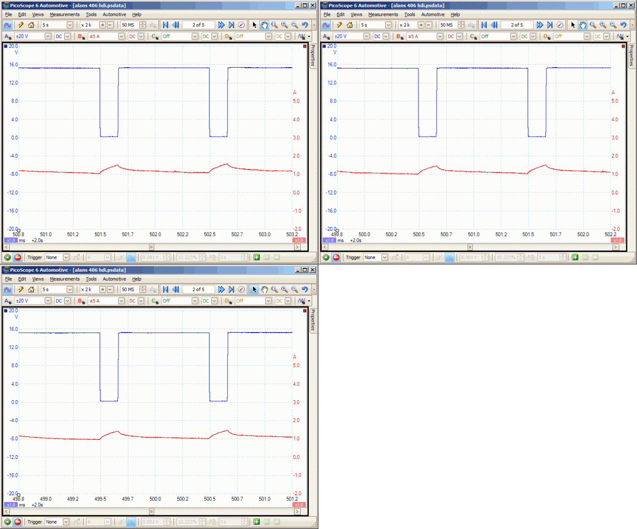
Anyway, back to the patient. This vehicle would occasionally display the fault at idle and with no driver intervention. By studying the duty cycle and current flow of the pressure control solenoid at the same time, then maybe a clue to the fault might be uncovered. Following on from my previous comments about larger screen time bases, here is a capture that demonstrates the point very well. Using what James Dillon terms as a "Helicopter View" we are taking an overview of the crime scene. It gives us a greater perspective of what is happening and things can often take on a greater significance when looked at this way. Here we are looking at the fuel pressure control. With fifty seconds per screen, there is a greater chance of seeing any significant shifts in the current flow and sure enough we can see exactly that, just that toward the end of the capture (as the red trace rises).

Blue = Regulator Duty Cycle
Red = Regulator Current
In the animation above, you can begin to appreciate the benefits of using the "helicopter view". In days gone by, we would be restricted to the view that we see when the waveform is zoomed to a very high level, as seen in the following animation:

Just imagine how quickly, an event would have flashed up on screen and then disappeared into the buffer (if you had that luxury) or possibly lost forever.
Many technicians will study either duty cycle or current flow, when looking at actuators, yet there is such value in looking with both duty and current traces combined. This capture from the pressure control solenoid highlights the point nicely. We are able to see both the command and demand relationships of the component, zooming into the detail we can see that whilst the current flow through the solenoid has increased dramatically, there has been no corresponding increase in command, witnessed in the duty cycle signal. This suggests that the PCM (Powertrain Control Module) has not initiated the change. The conclusion drawn from this waveform, is that the fuel pressure regulator solenoid, through a partial internal failure has demanded more current from the circuit. Replacing the component fix the issues with the vehicle.
Imagine the variety of conclusions that you could come to, if you had limited yourself to looking singularly at duty cycle or current and then being further limited to a small time capture. Don't restrict yourself with poor and outdated equipment and the practices that went hand in hand with it. More importantly if you have the equipment make sure that you use it to its full potential, don't be blinkered into a single approach to scoping. Enjoy the experience of studying events that many technicians are unable to access.
|