I had a customer's 2007 JEEP Compass , European Spec, fitted with the VW 2.0l TDi PD engine (code BLY). Unfortunately standard VAG software (e.g. VCDS) cannot communicate with this ECU (due to it being a JEEP). Communication via standard EOBD displayed "No Codes" although the check engine light was illuminated, and a misfire fault was present.
At this stage I needed to determine 3 things:
- Are all injectors receiving a signal from the engine ECU?
- Are all injectors draw an equal current?
- What cylinder is misfiring?
Firstly I connected Channel A to the alternator output terminal and using the Cylinder Balance test in PicoDiagnostics. I was quickly able to determine that only one cylinder was at fault, as three cylinders read between 98%-100% and one cylinder read at approx. 67% at 850 RPM. PicoDiagnostics was able to determine the correct engine RPM without any difficulty.
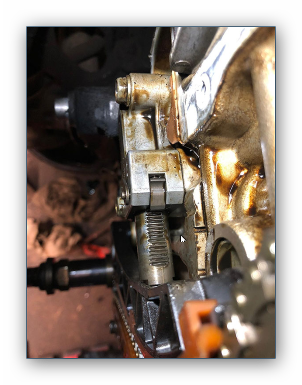
I now knew that the problem lay in one cylinder but had no idea which one. In the PD engines the injectors are fed via a multi-plug at the rear of the cylinder head. It is a very simple matter to connect a current probe to check the current waveform of all 4 cylinders via the common supply wire. It is also very easy with a second current probe to get the waveform of cylinder #1. Thus in seconds I was able to see that all 4 injectors were being actuated evenly and drawing very similar currents. This quickly eliminated any possibility of an electrical source being responsible for the misfire. I now needed to see which cylinder was misfiring. Normally I would check the Crankshaft Position Sensor (CKP) waveform , but:
- The wire is not very accessible in this engine and,
- Many of the more modern VAG PD engines use a Hall effect type CKP Sensor, and magnetic coil type sensors give a much clearer indication of a misfire.
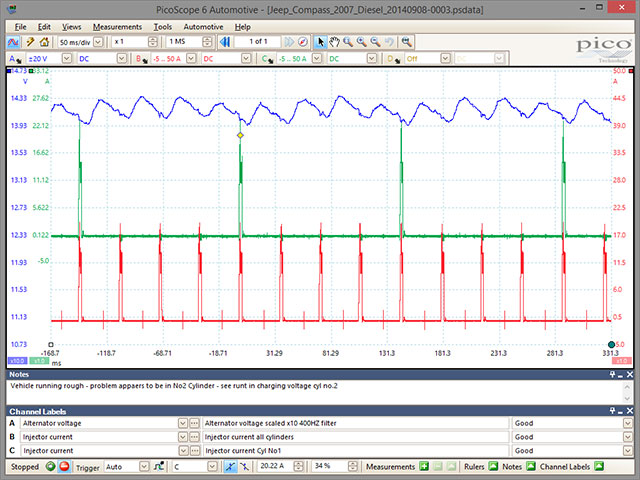
As I was already connected on Ch A to the alternator I decided to use the variation in alternator output voltage to find the misfiring cylinder. By setting the scaling of Ch A to x10, I was able to focus very clearly on the slight variations in the line voltage. By setting the low-pass filter to 400 HZ I was able to further enhance the signal and produce a very clear series of voltage readings which varied consistently with engine rotation.
Knowing that the firing order was 1342 I could immediately see without the use of tools apart from my PicoScope that the misfire was in cylinder #2, and that it was a mechanical injection fault rather than an electrical one.
To access those waveforms that are available online, please follow this link. Note that the full Waveform Library is only available via PicoScope Automotive software when connected to an Automotive PicoScope and requires a connection to the Pico Automotive Forum.

|