

A natural progression from the last topic of Ignition Primary Circuits is to analyse the different types of trigger signals used to switch the primary circuit at the appropriate time.
The following topic explains the common types of trigger variations along with example waveforms and a brief explanation as to its operation.
Permanent Magnetic Pick-up's
This particular type of pick-up generates its own signal and therefore does not require a voltage supply to power it. Recognisable by its two electrical connections, the pick-up is used as a signal to trigger the ignition amplifier or Electronic Control Module (ECM). As the metal rotor spins, a magnetic field is altered which induces an Alternating Current (AC) voltage from the pick-up. This type of pick-up could be described as a small alternator because the output voltage rises as the metal rotor approaches the winding, sharply dropping through zero volts as the two components are aligned and producing a voltage in the opposite phase as the rotor passes. The waveform is known as a sine wave.
The voltage produced by the pick-up will be determined by several factors, these being:
- Engine speed — the voltage produced will rise from as low as 2 to 3 Volts when cranking, to over 50 Volts at higher engine speeds
- The proximity of the metal rotor to the pick-up winding. An average air gap will be in the order of 8 to 14 thou, a larger air gap will reduce the strength of the magnetic field seen by the winding and the output voltage will be subsequently reduced
- The strength of the magnetic field offered by the magnet. The strength of this magnetic field determines the effect it has as it 'cuts' through the windings and the output voltage will be reduced accordingly
- A difference between the positive and the negative sine wave voltages may also be apparent, as the negative side of the sine wave is sometimes attenuate when connected to the amplifier circuit, but will produce perfect AC when disconnected and tested under cranking conditions
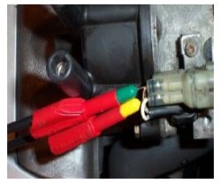
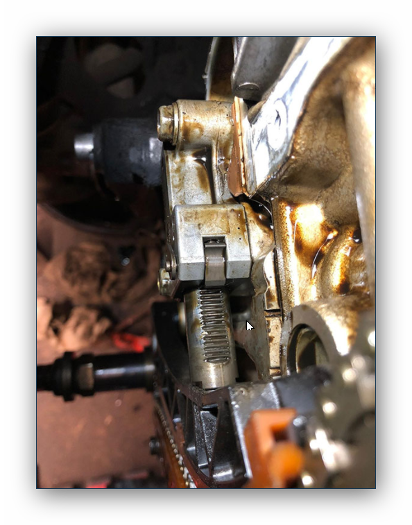
Figure 1.0
Back probe the two wire multiplug on the inductive pick-up fly lead coming out of the distributor's body, as illustrated in Fig 1.0. If the amplifier is mounted on the distributor body remove the amplifier and attach two small fly leads to the pick-up's output connections, and refit the amplifier (if you wish to test the pick-up whilst the engine is running). Crank or start the engine and observe the resultant waveform. Use a similar voltage and time scale to that shown in the example waveform Fig 1.1. A lower than anticipated voltage could be due to an incorrect rotor air gap, slow cranking speed or shorted pick-up windings. If you are using an AC volts setting on a multimeter the voltage recorded will be approximately 0.7 of the peak-to-peak voltage. Therefore if the data requires a 3 V peak-to-peak voltage, the allowable multimeter can be 0.7 of this reading.
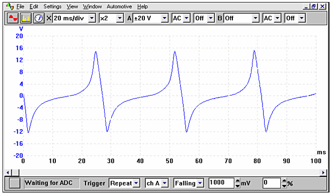
Figure 1.1
The above illustration (Fig 1.1) was taken with the engine at idle; the voltage will rise to around 50 V at cruising speed. The voltage output will vary between different systems manufacturers so it's important to reference to the appropriate specific data.
There are two types of permanent magnetic pick-ups these are called Annular and Limb. The distinguishing factor between the two types is that the limb will only have one pick-up point where as the annular will have a pick-up point per cylinder.
The pick-up will invariably be mounted on the distributor shaft and driven from the camshaft. They can be tested in several ways using either a multimeter or an oscilloscope.
Hall Effect Pick-up's
This form of trigger device is a simple digital 'on / off' switch which produces a square wave output that is recognised and processed by the ignition control module. The trigger has a rotating metal disc with openings; this passes between the electromagnet and the semiconductor. The effect of a magnetic field that is able to pass through one of the 'windows' will stop the flow of voltage. When the 'window' is closed the flow is reinstated. This action will produce a digital square wave that is understood by the Electronic Control Unit (ECM) or amplifier.
The sensor will have its characteristic three connections, which are: a live supply voltage, an earth and the output signal. The square wave when monitored on an oscilloscope may vary in amplitude; this is not thought to be a problem as it's the frequency that’s important, not the height of the voltage. When the voltage from the Hall effect trigger drops to zero volts, it fires the coil. This occurs when the 'window' on the metallic rotating vane opens.
Figure 1.2
Connect the ground connection of the oscilloscope to a known good earth and attach the voltage probe connection to the centre terminal. The three connections to the Hall effect pick-up are: the sensors voltage supply, an earth and the Hall effect output. The switched signal from the Hall effect is normally the centre pin (Fig 1.2). The Hall output has been captured in the example waveform shown in Fig 1.3. This voltage may vary between different manufacturers systems and the appropriate data should be sought.
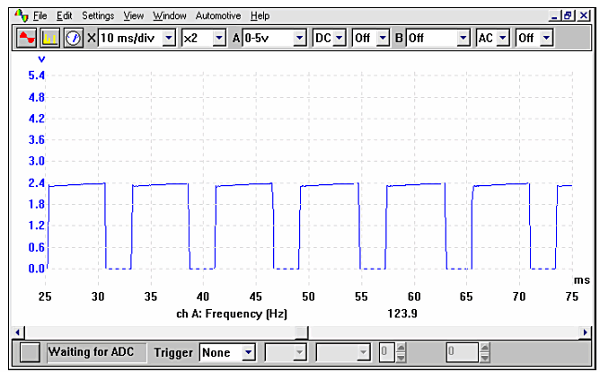
Figure 1.3
Inductive Crank Angle Sensors
This sensor know as a Crank Angle Sensor (CAS) or sometimes Crankshaft Position Sensor (CPS) can be mounted in various positions and can be located near the front pulley, to the rear of the engine into the flywheel, in the side of the engine block or within the distributor. The output signal produced is used by the Engine Control Module (ECM) to determine the exact position of the engine.
On an inductive CAS a resistance value should be seen between the terminals. This type of sensor is the most popular but Hall effect and AC excited sensors are also used in some engine management systems. The inductive sensor is normally a two wire device, however some manufacturers use three wires, the third being a coaxial braid to keep out any HT interference that may interrupt and corrupt the signal seen by the ECM.
The output voltage produced on this sensor will be vehicle specific and the output will reduced by any of the following three factors:
- The sensor air gap will in some cases be fixed and is non adjustable, while on other vehicles the air gap can be adjusted and measured using feeler blades. A larger air gap will decrease the voltage output from the sensor
- A failing sensor with shorted windings will also reduce the voltage output, while a sensor with an open circuit will have no output at all. The condition of the winding inside the crank angle sensor can be determined by conducting a resistance test with a multimeter
- A slower than anticipated cranking speed may also cause the output to be low; the characteristics of this being that the engine will not start when cranked, but starts if the engine is 'bump started' causing the engine to rotate faster and producing sufficient voltage to trigger the ECM. A large air gap can also give the same symptoms.
Crankshaft position sensors tend to fail as they become hot and the windings become open circuit, in this instance the engine will stop, but restarts if left to cool down.
For test purposes, connect the oscilloscope in exactly the same way as you would when testing an inductive pick-up located within a distributor. The resulting waveform should look similar to the example shown in Fig 1.4. This particular waveform was captured while the engine was cranking, this is evident from the differing peak-to-peak voltages seen. This is due to the engine reaching a compression stroke, at which point the engine slows momentarily and the voltage is lower. As the engine speeds up before the next compression stroke, the voltage increases.
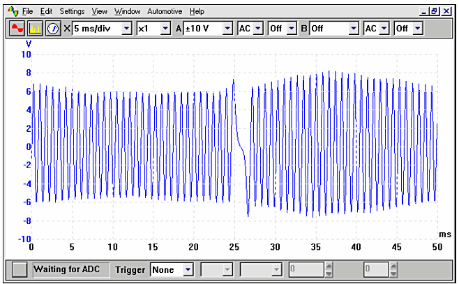
Figure 1.4