|
|
||||
| Log In | ||||
|
| ||||
| ||||
| ||||
| ||||
| ||||
| ||||
| ||||
| ||||


The Versatile Scope - Part 2By Nick Hibberd
Hibtech Auto-Electrical Diagnostics Here`s another example of the oscilloscope being used as a versatile fault-finding tool. The fault itself is for the most part incidental here, but it demonstrates the level of information held within a recorded trace and how quickly you can be put on the right diagnostic path. Fiat SpeedometerThe case was a 1999 Fiat Bravo 1.6L with a complaint of intermittent speedo operation. The speedo would read correctly up to cruise speeds then would suddenly drop to almost zero. A new speed transducer on the gearbox had already been installed and a dealership had recommended a new instrument cluster be fitted at £400 ; another incident where the cost of a new electrical component may render a vehicle uneconomical to repair. This car initially arrived to me as can it be repaired? I advised first to verify the fault and then decide what action to take, with a likely task of inspecting the instrument cluster in detail. But the first step was to see the fault. The car was road-tested to recreate the complaint. While cruising at about 40 mph, it wasn`t long before the speedo dropped sharply to almost zero. Repeat testing showed similar results and I noticed it wasn`t directly linked to a certain speed: it was sometimes 30 mph and sometimes 50 mph before the needle dropped. The next step was to validate the speed signal arriving at the instrument cluster. If the signal displays the correct frequency in proportion to vehicle speed then focus of the investigation would rightly fall on the instrument cluster as already reported. A speed signal can arrive at the instrument cluster in many forms i.e. through a serial line with the Engine Control Module, or a direct line from the ABS system, or through CAN, or in this application using a simple gearbox transducer connected directly to the instrument. 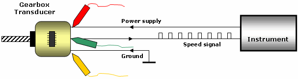 The instrument cluster provides the sender with a 12 V power supply and a signal reference voltage of about 5 V. Under normal operation the sender modulates this signal line between ground and 5 V creating a square wave pulse. As the vehicle speed increases, the frequency of pulses increases in proportion. TIP: The instrument calibration is matched to the gearbox transducer, its drive, and the road wheels to generate a specific number of pulses over a given distance. Altering the road wheel circumference (modifying rims and tyres) will throw out the calibration and cause speed to be registered incorrectly.
As a general starting point, the scope was hooked up to the speed sender by monitoring the two power cables in and the speed signal out. It`s best to collect as much information about the fault as possible. 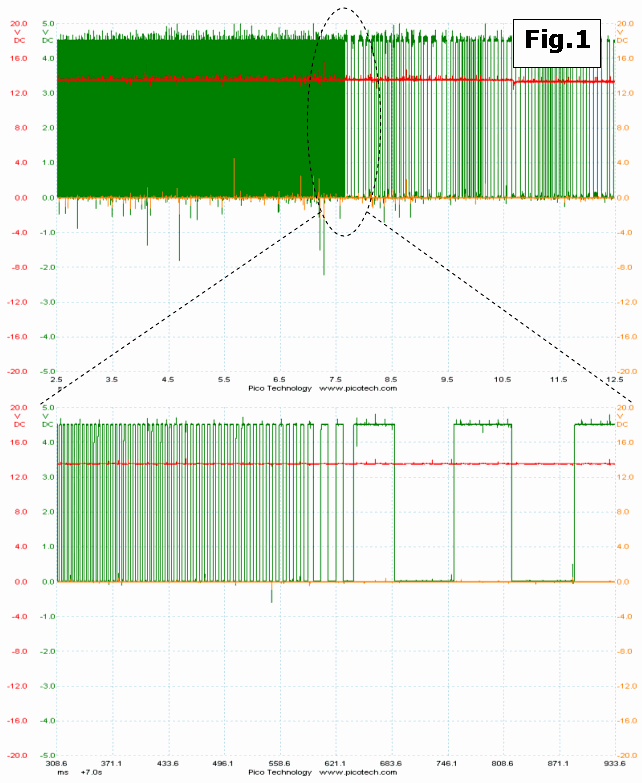 Fig.1 was recorded during a fault event where at steady cruise speed the needle suddenly dropped, and judging from the results this investigation has taken an unexpected turn. There are several important observations to make:
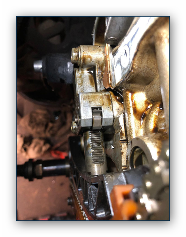
By applying these key observations it is possible to localize the fault to the sender or its drive connection with the gearbox. From this result, an appropriate test plan can now be formed. ConclusionThe fault was traced to a damaged plastic drive insert that fixes to the gearbox. This drive insert is separate from the electrical transducer and did not get replaced by the previous repairer, so obviously it wasn`t spotted. This insert is a rotating shaft with a female sliding contact which had become worn and lost its grip with its male counterpart on the speed transducer, and as vehicle speed increased this was causing the two mating shafts to lose each other. A new drive insert rectified this complaint. I`ll leave the obvious “parts fitting” approach for you to scrutinize. The purpose of this example and others is to highlight the importance of a recorded trace, which by a correct interpretation of the information held within can lead to a trustworthy test route.
|
||