

In this tutorial we will be looking at the relationship between the Primary picture and the Secondary HT output, and monitoring spark burn times and HT voltages.
The example waveform (Fig 1.0) shows the exact relationship between the ignition's primary circuit and the secondary output. The primary circuit transfers its characteristics into the secondary through ‘mutual inductance’ and will mirror the primary exactly.
The blue trace shown in the example is the Low Tension (LT) signal, measured from the coil's negative terminal (marked number 1). The red trace is the High Tension (HT) output voltage measured at the king lead. In the example, both waveforms show exactly the same burn time of 1.1 milliseconds (ms).
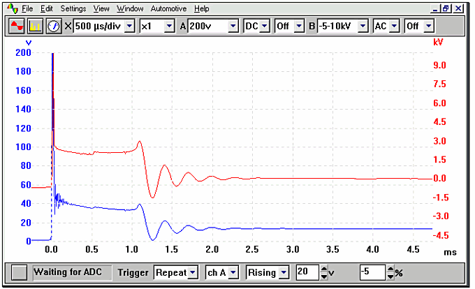
Figure 1.0
Situated within the coil's primary winding is the secondary winding. This winding is coiled around a multi-laminated iron core and has approximately 20,000 to 30,000 turns. One end is connected to the primary terminal and the other to the coil tower. The High Tension (HT) voltage is produced by mutual induction between the primary winding and the secondary winding, and the central soft iron core intensifies the magnetic field between them.
On a distributor system, the secondary HT voltage produced by the coil is allocated to the appropriate spark plug via the contacts inside the distributor cap. This system is quickly becoming obsolete due to the introduction of the DIS and coil per cylinder systems with fewer moving parts and wear factors. The voltage measured at the spark plug is the voltage required to jump the plug gap in varying conditions, and will be determined by any of the following:
| The plug kV's will be increased by: | The plug kV's will be decreased by: |
|---|---|
| Large plug gaps | Small plug gaps |
| A large rotor air gap | Low compression |
| A break in a plug lead | Rich mixture |
| A break in the king lead | Incorrect ignition timing |
| Worn spark plugs | Tracking to earth |
| A lean mixture | Fouled plugs |
| Rotor to reluctor misalignment |
The plug kilovolt (kV) requirement of older engines tends to be lower than that of the modern engine, as the later designs will run higher compression ratios, leaner air/fuel ratios and have larger spark plug gaps. The modern engine with Distributorless Ignition System (DIS) has all the advantages of a constant-energy electronic ignition system, but with the added bonus of the distributor cap, king lead and rotor arm being eliminated from the system. Reliability problems from dampness and tracking are now almost eliminated. DIS has its own drawbacks by having half of the plugs firing with an acceptable negative voltage, while the other half is fired by the less acceptable positive polarity. This will have the effect of pronounced plug wear on the positive fired plugs.
This system, because of its nature, will fire the plugs each revolution, instead of every other, and is known as a wasted spark system. This does not mean that the plugs will wear at twice the normal rate, as the wasted spark is on the exhaust stroke, and is therefore under no compression. If the spark plugs are removed after several thousand miles and examined, it will show that two of the plugs have relatively square electrodes, while the plugs that have been fired positive will have pronounced plug wear.
Secondary voltages and Waveforms
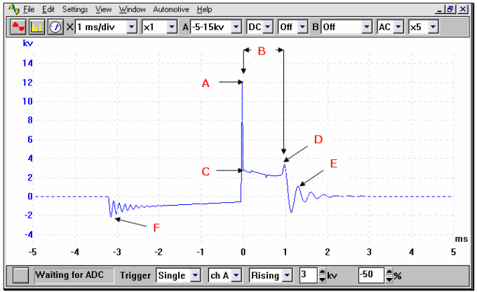
Figure 1.1
The ignition secondary picture shown in the example waveform (Fig 1.1) is a typical picture from an engine fitted with electronic ignition. The waveform is an individual secondary High Tension (HT) picture that can be observed one cylinder at a time.
The secondary waveform shows the voltage required to jump the plug's electrode (A), and (B) the length of time that the HT is flowing across the spark plug's electrode after its initial voltage to jump the plug gap. This time is referred to as either the ‘burn time’ or the ‘spark duration’.
In the illustration shown, it can be seen that the horizontal voltage line in the centre of the oscilloscope (C) is at fairly constant voltage of approximately 3 kV. This voltage is referred to as the Sparkline kV. This voltage is the voltage required to maintain the spark flow across the plug's electrode, and is determined primarily by the secondary resistance within the HT circuit. From the 0 ms point on the scope to point D is the spark duration, in this case around 1.0 milliseconds. The waveform is then seen to drop sharply into what is referred to as the ‘coil oscillation’ (E). The coil oscillation should display a minimum number of peaks (both upper and lower) and at least of 4 - 5 peaks should be seen. A loss of peaks on this oscillation shows that the coil needs substituting. An example of a faulty coil and the subsequent loss of oscillations can be seen in Fig 1.2. The oscillation seen at point (F) is called the ‘polarity peak’; this voltage will be of the opposite polarity to the plug firing voltage as this is created when the magnetic flux is initially built, or at the start of the dwell period.
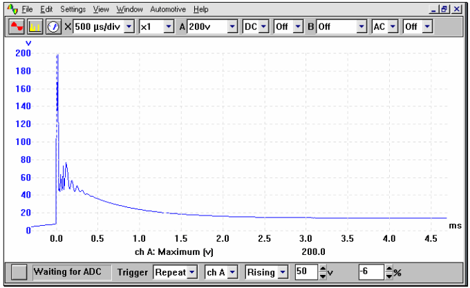
Figure 1.2
SAAB CDI Ignition
This particular system is different from the conventional magnetic inductive system and is called Capacitor Discharge Ignition (CDI). CDI was used on a few vehicles in the late 60s early 70s, but is now seeing a revival in this innovative system.
The ignition pack consists of individual coils that are mounted directly onto the spark plugs and are housed in a ‘cartridge’ , located between the engine's camshafts. As well as housing the ignition coils and spark plug connectors, the cartridge also contains the capacitor and the charging transformer, plus some other circuitry, as Direct Current (DC) voltage cannot be multiplied by a transformer until it has been converted into Alternating Current (AC) voltage — usually by means of a oscillator.
The 400 volts contained within the capacitor will be discharged into the appropriate coil from signals received from the Electronic Control Module (ECM). This is mainly where this system differs from the conventional ‘Coil per Cylinder’. The 400 volts are discharged to the positive terminal of the coil and the coil negative is a permanent earth. Where as a typical system will supply 12 volts to the positive terminal of the coil and 400 volts is seen on the negative side from inductance.
All of the connections in and out of the cartridge are at 12 volts or less and primarily terminate at the ECM. When the engine is cranked, the ECM will fire cylinders 1 and 4 together and cylinders 2 and 3 as wasted sparks, with every Top Dead Centre (TDC), until the ECM has determined which cylinder is on the combustion stroke (as opposed to the exhaust stroke). The ECM takes its reference from a Hall effect sensor that is located to the rear of the front pulley.
To aid starting when low cranking speed is seen, the ECM will continually fire the plugs up to 60° after TDC with a continual arc across the spark plugs' electrodes. This process will continue until the engine speed reaches 850 rpm.
If the engine fails to start and the ignition key is returned from the crank position, a sequence of sparks are fired across the plugs to free them from any fouling and to clear any excess hydrocarbons left in the cylinders. Great care needs to be taken when working on secondary ignition systems and even more so on this particular one!
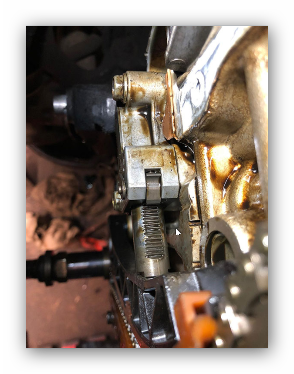
Figure 1.3 shows a direct ignition system, as used by Saab.
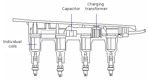
Figure 1.3
All the example waveforms used were recorded using a Pico automotive oscilloscope . Other manufacturers' equipment will have different voltage ranges but the resultant picture should be very similar. Please remember that using a higher voltage range will result in the waveform appearing to have a lower amplitude, although the overall voltage will be the same.