

Due to the high voltages involved in secondary ignition systems, it is not possible to make measurements by direct connection, attempting to make a direct connection will almost certainly damage the measuring instrument.
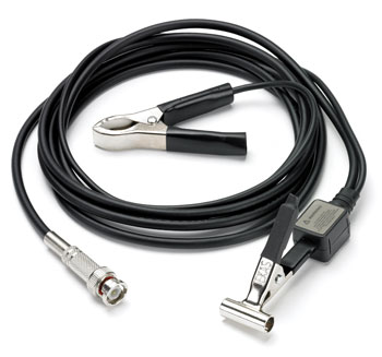
The PP178 is a capacitive pickup which simply connects around the insulation of an ignition circuit component such as a plug wire, this avoids the need for direct connection.
The PP178 comes with a shielded 1.8m (6 foot) lead. It is suitable for use with conventional ignition systems and most HEI and DIS systems. Our library of Automotive Waveforms contains example waveforms captured using a Pico automotive oscilloscope and the PP178.
Although ideal for use with a Pico automotive oscilloscope, the PP178 pickup can also be used with most other makes of oscilloscope provided they have an waveform invert option. (The information on scaling below is only applicable to Pico oscilloscopes.)
How to use the PP178 [MI074] Secondary Ignition Pickup
Safety precautions before use:
- Keep the lead away from pulleys and other moving parts
- Keep the lead away from heat
- Never let the pickup come in direct connection with primary or secondary voltage (otherwise the PicoScope may be damaged)
- Always use the ground clip
- Do not let the metal portion of the pickup contact a ground
Connecting the PP178:
- Connect the PP178 to the automotive oscilloscope before connecting to the vehicle
- Connect the ground clip to a good ground on the vehicle
- Connect to vehicle
For...
- Standard Ignition: clip the pickup around the coil wire (or one plug wire at a time)
- Intergrated coil: clip the pickup around the central location on the distributor cap
- DIS: clip the pickup around one plug wire at a time
Using the PP178 [MI074] with PicoScope Software
Displaying a waveform from the PP178 Secondary pickup is fairly trivial, just plug it into the automotive oscilloscope and set the timebase, voltage range and trigger. Your waveform should look like the one below.
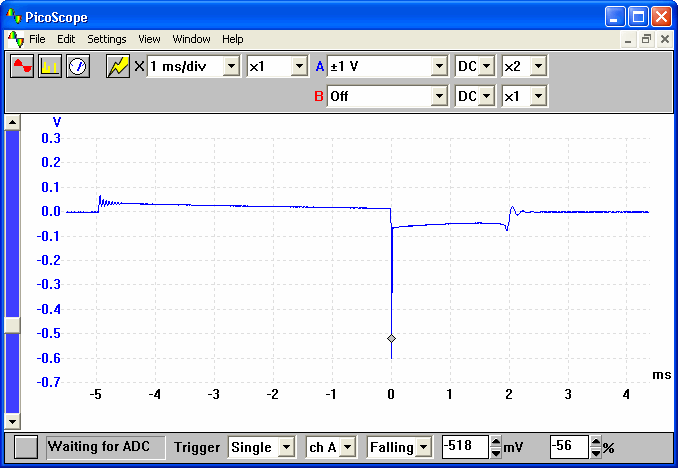
There are however 2 problems with the above waveform, firstly as secondary ignition is inverted with respect to primary, many people consider the waveform to be upside down. The second problem is that the scaling is incorrect, the probe attenuates by a factor of 10000 so the amplitude displayed is wrong.
Fortunately, using PicoScope's custom range options it is easy to set a extra voltage range up for this probe. First select custom ranges from the settings menu. From the custom range dialog, click add then fill in the form as shown below:

The above settings both scale the results and invert the result (5000 mV scales to 50 kV). Once you have entered in the information, click on 'OK' then select File | Save Settings. If you now click on the drop down menu that selects the voltage range, you will see a new 50 kV range for use with the probe.
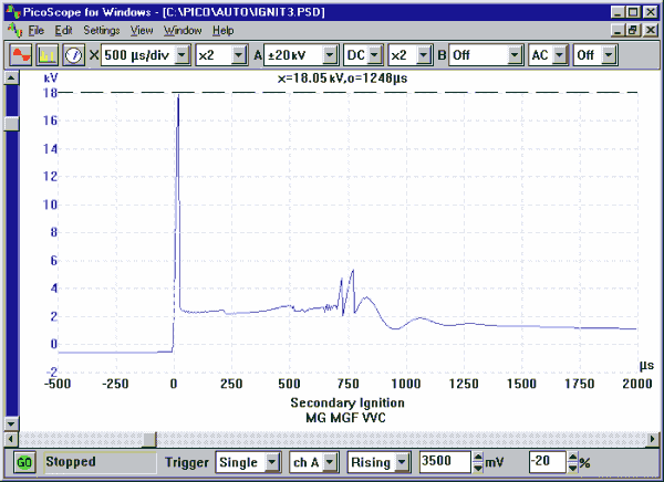
If you wish, several different ranges can be added in this manner. The graphic below shows a 20 kV range — note the ruler is being used to measure the max amplitude.