


The car had an intermittent drivability complaint, bogging down under acceleration with no MIL flagging. The customer insisted that it wasn’t just intermittent; it was very intermittent. First things first: I connected the scan tool to see if any DTCs had been logged. It was here that this investigation took a sharp turn.
The scan tool oddly came back with No Communication Possible, and whenever I see this I automatically think, what have I done wrong? It’s only natural to think this because computers don’t make mistakes, do they? I ran back through everything but it was still the same.
I checked other modules and quickly noticed No Communication on a lot of them. This is typical of diagnostic line failure, and already a mental game plan was beginning to form. Before doing anything else, I made the customer aware of what I had found and that this was a vital investigation in itself before I could begin to address his original complaint.
If I am dealing with a diagnostic line failure, then a cabling short to battery negative or positive is the most likely cause. I know from past dealings with this make of vehicle that nearly all connected modules run to one pin on the OBD socket, which isn’t going to help things because now my suspected fault could be anywhere on the car.
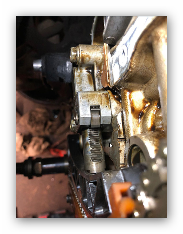
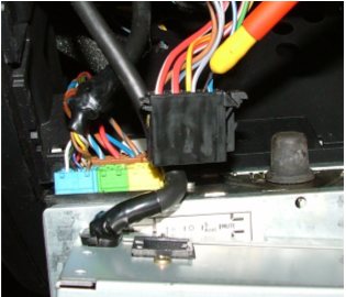
It was time to hook up the oscilloscope to get a clearer picture of the fault. Monitoring the diagnostic line electrically is a little awkward on this model, to say the least, so I opted for a known connection at the back of the radio which actually could help the diagnosis.
In this picture I’m connecting to a module away from the OBD socket and my next move will depend on what I capture. Because I’ve already decided that other modules apart from the engine are affected, I’m anticipating that every capture I get here will be the same for the rest of the diagnostic line and its connected modules. Initially I look for a voltage level present, usually near battery voltage, and then as the scan tool attempts a handshake I look for a pulsed ground in a code sequence. Because each module shares the diagnostic line, only one will respond to a certain code given by the scan tool, leaving all others ignoring it. Enough theory — let’s have a look.
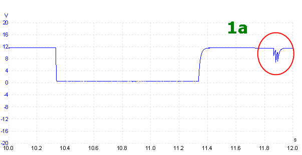
For a diagnostic line problem, I like to take a wide view and then zoom in later. This helps to see the scan tool handshake, which can be lengthy until the module responds, and also any abnormalities that might be lurking.
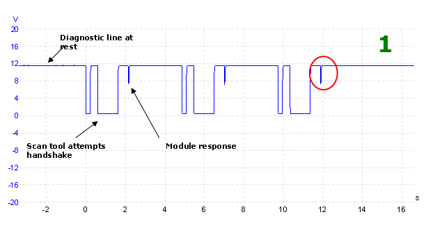
On the face of things there is not a lot wrong. We see a good handshake structure, with good high and low voltage levels present. It also tells me that I’m not dealing with an open circuit problem between the scan tool and the modules. What isn’t clear at the moment is the integrity of the module’s response, but this could be due to the PC struggling to display the fast dialogue reply with the long time base. Let’s zoom in for a better look.
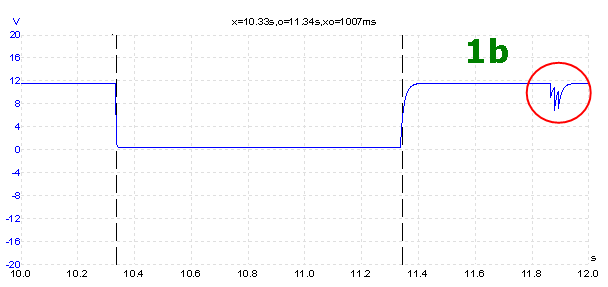
Now things don’t look so good. The highlighted section which is supposedly our module reply is an immediate cause for concern. There’s something trying to break through but it certainly isn’t binary. It looks more like a sawtooth pattern. The same signal “arch effect” seen in the module response can also be seen in the rising edge of the handshake. This is potentially a big problem and worth pointing out.
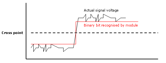
In binary signals, there is always a threshold of operation, and the voltage doesn’t have to be full on or full off for a module to recognise a valid binary bit. There is a crossover point where a module understands the difference between high and low states. If noise spikes don’t cross this threshold, then the module won’t see them and detect the wrong state. Here I’ve chosen a threshold of 5 volts as an example.
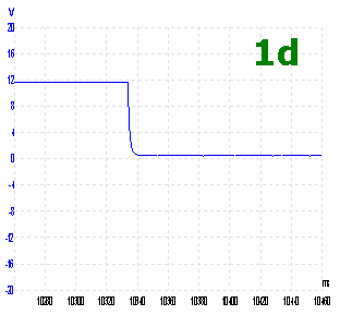
In the capture 1b you can see that, because the rising signal edge has an “arch effect” as it returns to rest, it will have an effect on the rise time and thus the overall handshake time from the scan tool. I recorded the rise time here to be around 23 ms (0.023 seconds), which I don’t consider normal, but the time between state changes of 1.007 seconds wasn’t enough to prevent the module from responding, however wrongly, to the handshake.
So what’s causing this? At the moment I’m not considering a hard wiring fault, but rather leaning towards a module problem. The described “arch effect” in the signal appears very controlled, neat, and clean. This type of control is indicative of a resistive-capacitive (RC) circuit, but has no place in binary signalling. This is an issue at an electronic level.
On closer inspection of a falling binary edge, we can see a similar characteristic. I would have expected the binary structure to be much more definite than shown at this time scale.
At this point, I took a step back and jotted down some ideas in diagram form. This has helped me in the past to spot problems that were not originally anticipated. This time, the most likely cause I could come up with was as follows:
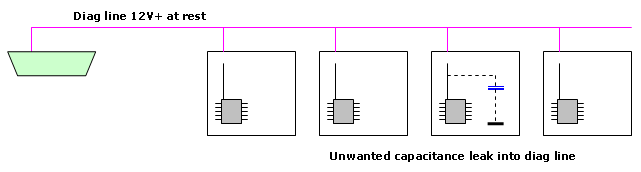
I’m suspecting a capacitance leak into the diagnostic line, and that the capacitance is already connected to ground potential, or certainly close to it. Here’s my reasoning.
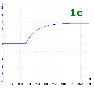
The diagnostic line voltage at rest is derived from a high-resistance source inside the connected modules, including the scan tool that is now also connected to the line. Only a very small amount of current is needed to pull this voltage down to 0 V; that’s all the scan tool does. With the line voltage at rest, our suspect capacitance will already be charged. As the scan tool handshake pulls the line voltage down, the capacitance is also forced to dump its stored charge to ground, but not without putting up a fight first when we see the small exponential curve at the base in extract 1d. Now the capacitance is at near ground potential for the duration of the binary low state. When we see the binary low state released in extract 1c, our suspect capacitance charges up and once again we see the characteristic exponential curve. Notice how the two binary edges are affected to different degrees. This is because the scan tool ground command comes from a low-resistance source pulling the signal down at the beginning, while the diagnostic line has a higher resistance pulling the signal back up at the end.
Of course, none of this theory is any use whatsoever, as I’m still left with the question: where’s the problem?
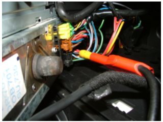
The engine module is a bit of a pain to gain access to under the wiper scuttle trim, so I started the search within the passenger cabin. I stripped the underside of the driver’s dash panel to have a look around. A Convenience Unit lives behind here, and then I planned moving on to the instrument panel. Then it dawned on me that the radio was obviously a module too...
I pulled out the power ISO connector and retried the scan tool: Connection Established.
Incredible! It was staring me in the face. The whole diagnostic system was now back in operation.
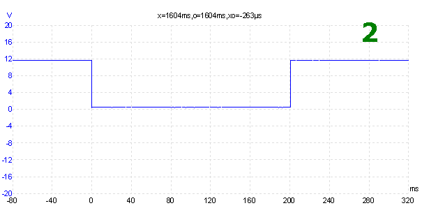
Capture 2 was a segment of the handshake now: perfect.
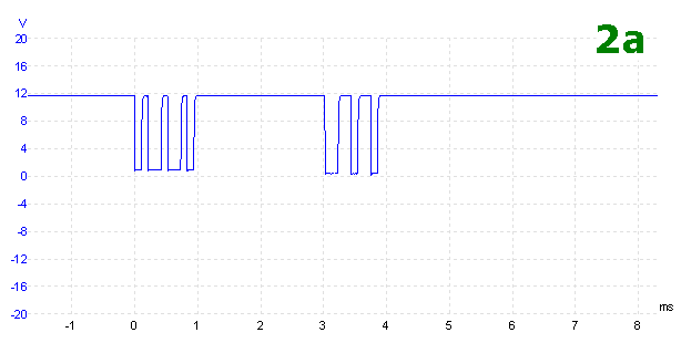
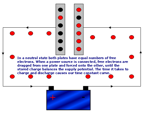
Capture 2a was taken with the engine module sending a full data stream to the scan tool. With the radio connected (fault present) the signal didn’t stand a chance of developing a full “bit”, because our stray capacitance stored enough energy to keep the diagnostic line potential quite high. We come back to time constants of RC circuits, where a capacitor is allowed to charge up from a power supply and then discharge into a load.
The scan tool handshake is long in comparison to the full data stream, and it managed to create a defined binary bit without letting the stray capacitance interfere too much.
I isolated the diagnostic line connection from the radio and informed the customer of the situation. He didn’t seem too bothered that his radio was missing a diagnostic line.