


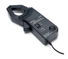
The TA019 current clamp is ideal for use with the ADC-212, 3000 or 4000 series automotive oscilloscope to display starter current waveforms, charging currents and for performing quick compression tests (see waveforms below).
The current clamp can measure up to 600 A (AC or DC). In use there is no need to break into the circuit or disturb the isolation as the opening jaws simply clamp around the current carrying conductor. No electrical contact is required.
Connecting the Current Clamp
The TA019 current clamp features a BNC connector and can be plugged directly into the scope.
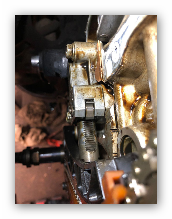
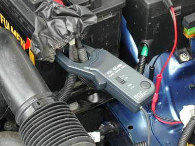
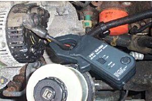
Once connected to the scope switch the current clamp on (green LED should light) and then clamp the jaws around the current carrying conductor as shown.
Using the TA019 Current Clamp with PicoScope
The current clamp is calibrated to provide 1 mV of output for every 1 A of measured current. A quick check that the clamp is working can be done by measuring the current drawn when a cars headlamps are switched on. To do this start PicoScope and select 100 mV range (DC coupled) on either the scope or the meter. Connect the clamp around the ground connection to the car battery. With nothing on the car switched on the reading on PicoScope should be near 0 mV. Now swich the headlamps on, the reading should jump up a few mV (1 mV per amp of current drawn.) If the reading in fact jumps down, dont worry—current clamps are directional, just reverse the clamp on the conductor.
Using PicoScope it is easy to scale the output from the clamp from mV to Amps. First select Settings | Custom Ranges from the drop down menu and click on the ADD button.
Next fill in the scaling information as shown on the right. This simply scales from mV to Amps and provides a 0 to 600 A range (the maximum the clamp can measure). Other ranges can be added in a similar way, for example for a 0 to 100A range change each occurrence of the number 600 to 100. More information on scaling can be found in PicoScopes online manual.
When you have filled in the scaling information press the OK button (twice) to return to the main menu. Now select File | Save Settings to save your custom range. This custom range now appears in the drop down list of voltage ranges (see examples below.)
Example 1 : Measuring Starter Current
The example below was obtained by measuring the current in the battery to starter motor lead. The high initial peak of current is caused by the starter motor struggling to overcome the inertia of the stationary engine. As the engine begins to rotate, the current drops. Once the engine has fired, the starter motor is disengaged and the current drops to zero.
As well as the scaling, note how PicoScope is set to trigger off the initial peak of current. A small amount of pre-trigger (-10%) has been used so that events before the trigger can be observed.
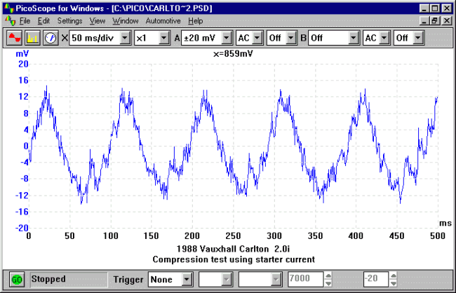
Example 2 : Compression Testing
This example again measures starter current, but this time on a engine that will not fire. Notice the oscillation in the current drawn, this is caused as each cylinder compresses. Measuring starter current in this way can be used as a quick compression test. Cylinders with low compression are easier to turn, so have a smaller peak. By using the second oscilloscope channel to also display No1 cylinder ignition, it is easy to locate which cylinder is causing the problem.
In this example we are not interested in the steady DC current drawn by the starter motor, instead we are concerned with the AC ripple caused by the cylinders compressing. For this reason we have AC coupled the signal from the current clamp.
Example 3: Measuring Charging Current
For this final example, alternator charging current and voltage was measured using the meter function in PicoScope. The current clamp needs to be switched on and facing the correct way. There is an arrow pointing to the battery positive ( ) on one side and an arrow pointing to the battery negative (-) on the other side. Incorrect connection will lead to the incorrect polarity of the reading, in this case the alternator is generating current and we would expect to see a positive reading.
The clamp needs to be positioned around the wires on the back of the alternator. If this is not possible, then the clamp can be positioned at the battery positive cables, if possible identify the wire that connects the alternator to the battery. By clamping all positive wires at the battery the clamp will read a balance between loads and the charging current.
Additional Advice for Low Current Measurement
Although the current clamp is designed primarily for measuring 'high' currents, the high resolution and flexible input ranges of the PicoScope 4000 Series allow much lower currents to be measured than with most automotive oscilloscopes.
To make measurements at low currents, the following advice may help:
- Before connecting the clamp, use the zero adjust wheel to trim out any offset
- If possible, loop a number of turns of the cable to be measured through the jaws. The actual current is the measured value divided by the number of turns
- At low currents, noise pickup from ignition / injectors etc may be a problem. Keep the clamp and its connecting cable as far away from the noise sources as possible