|
|
||||
| Log In | ||||
|
| ||||
| ||||
| ||||
| ||||
| ||||
| ||||
| ||||
| ||||


By Nick Hibberd
Hibtech Auto-Electrical Diagnostics The vehicle was a Fiat Ducato 2004 2.8 JTD with a repetitive complaint of poor starting. The engine would crank at good speed but took a while before it eventually fired, and once started the vehicle drove fine. The customer was adamant that this problem only reared its head after a cam belt failure and major top-end repair work. The vehicle got passed round his local garage network with different verdicts ranging from timing misaligned to new sensors fitted all round. The vehicle arrived at one of my trade clients, who understandably didn't want to take on someone else's leftovers, and the fault was passed over one more time for my opinion. Checking the system with the scan tool, I found one DTC logged relating to ENGINE RPM/CAM SYNCHRONISATION. This sheds light on the attached history and the new CMP and CKP sensors already fitted. The DTC would reappear each and every time the vehicle was cranked and, once the vehicle was eventually started, could be erased until the next start-up. Monitoring live serial data, I saw that the synchronisation PID mirrored the symptoms, taking a long time before it registered a "YES"; incidentally, the same time as the engine fired. This correlated nicely and gave a good indication of where to focus the test plan. Until the ECM is happy with the cam/crank indexing, it cannot identify the cylinders and subsequently deliver fuelling.
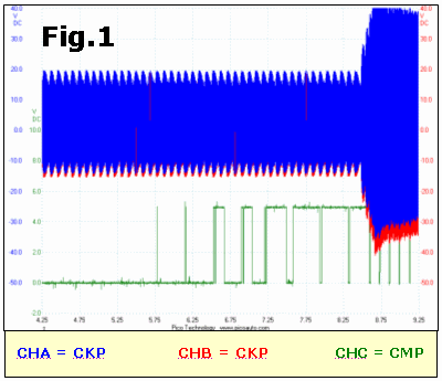
The scope was hooked up to the crank sensor and cam sensor outputs. This vehicle application uses a Variable Reluctance CKP (sine wave), and a Hall-effect CMP (square wave). Fig.1 was captured during a typical poor starting event and shows an obvious problem with the CMP signal. There is no signal at the beginning of the crank command with a progressive signal structure emerging as cranking continued. Towards the end of the trace we see the signal stabilise enough for the ECM to recognise a good indexing and allow a successful start. From these initial findings the CMP sensor circuit needs to be explored in more detail.
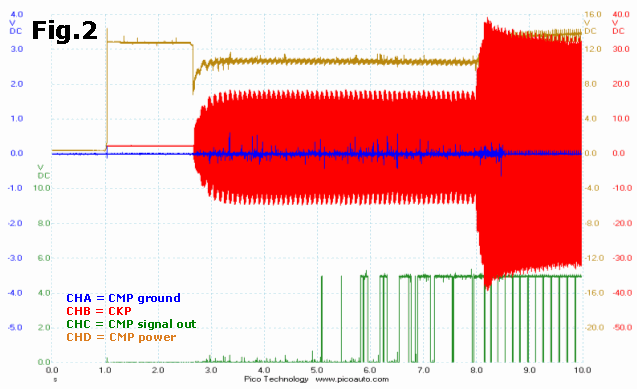
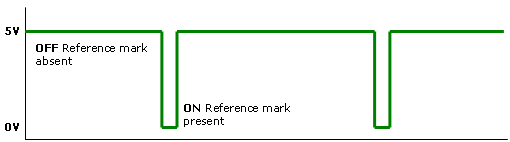
Fig. 2 shows another poor start event with the same delayed and erratic CMP signal. Here we are monitoring the sensor's power supply and ground which remain good throughout the fault. Although the signal line is erratic, there doesn't appear to be any voltage leak outside the normal operating window: the two states 0 V and 5 V remain consistent as opposed to drifting to other potentials. Also the transitions between the states are clean switching, giving an excellent DC pulse, just not the correct pulse duration and not in sync with the crank. For the moment I'm not thinking that this fault is cabling or connection related. Our problem is that the CMP sensor is unable to generate a good pulse at the start of the crank command. Why?
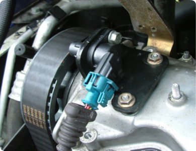
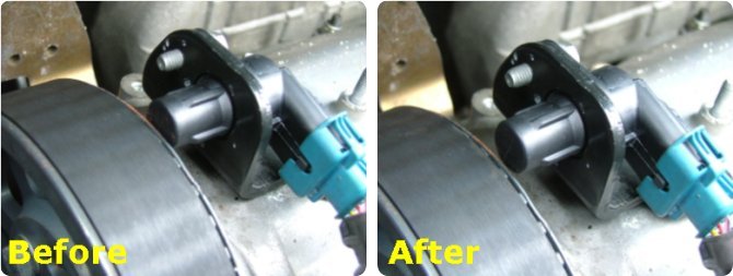
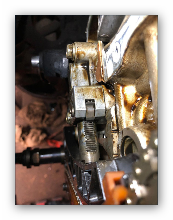
On this engine the CMP is hard to miss, sitting proud on the rocker top next to the cam gear. The sensor itself is bolted onto a bracket and can only be mounted one way. But the sensor mounting bracket has quite a lot of lateral movement available towards/away from the cam gear. On a positive note, this can be an advantage to fine-adjust any discrepancies, but also leaves the assembly open to agitation or becoming disturbed. A common problem associated with CKP and CMP sensors is proximity between a rotating reference mark and the sensor face: the gap can be too large for the reference mark to interrupt the sensor's magnetic field. Often this gap cannot be seen and although the external surface mount of the sensor appears a flush fit, this is far from conclusive that the signal output will be good. The ONLY reliable test is monitoring the signal through an oscilloscope and deciding from there if the signal is suitable or not. Fortunately we have a ringside seat for examining this CMP gap, which can confidently be ruled out. However, there is something else to consider. We have to remember this sensor uses the Hall effect principle. An internal current-carrying IC is placed in a small magnetic field, and as our reference mark moves into the sensor's field this changes the strength of that field and deflects the IC current path creating a new millivolt potential across the IC - it's this millivolt potential which is the Hall voltage. From here the voltage is evaluated internally and emitted as a DC pulse switching between ON and OFF states.
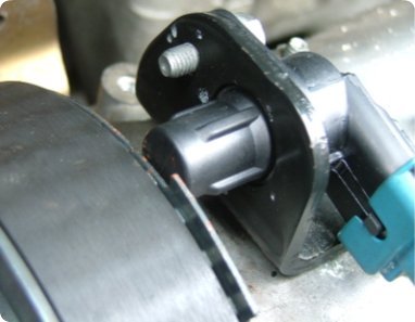
One of the advantages of the Hall effect is that it is not speed-dependent, so it will recognise a given state at any speed, even at stationary. This operational characteristic is key. If we overlay this information to our CMP sensor and its mounting position we see a problem. Almost a third of the sensor's face is obstructed by the cam gear during periods where the reference mark is absent. This OFF state is likely enough to fall into the magnetic reach of the sensor and incorrectly report that a cam reference is present.
The mounting bracket was removed and spacers placed underneath to elevate the assembly away from the cam gear, making sure the cam trigger would comfortably pass across the sensor's face. This should now give the sensor a good magnetic distinction between the two states and hopefully improve starting performance.
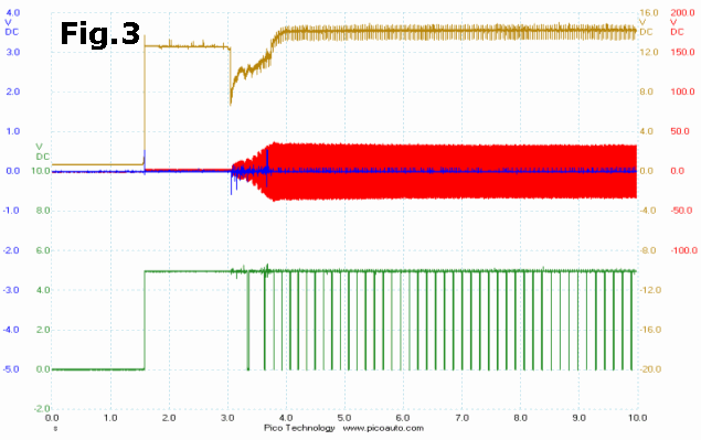
Fig.3 is a typical capture taken after the bracket adjustment and shows an immediate response from the CMP together with a quick start-up; overall much better. The capture also reports a return of the CMP's 5 V bias line when the ignition is switched on. Back in Fig.2 with the ignition on, our CMP's output remained in the ON state (0 V), which we can now attribute to the cam gear hanging in the sensor's magnetic field. This was an unusual problem. The vast majority of CMP sensors are either fixed into the cylinder head or fixed adjacent to a diesel pump, where little user thought need be applied. It was clear that someone in the vehicle's history had understood the importance of having a speed/position sensor close to a reference gear. However, as this fault-find demonstrates, it is not the only operational factor to consider. Not related to this particular fault, but did you notice the recorded CKP signal levels? 32 VAC during cranking and 65 VAC at idle: surprising components are VR speed sensors. These values were a little aggressive and it was worth spending a bit of time tweaking this voltage down to a more manageable level. As a benchmark I use 15 to 20 VAC at idle speed, which usually creates a good induced voltage at cranking, and keeps a safe voltage at high rpms. Tip: Don't verify that the sensor is working by licking the end wires! PicoScope data files
|
|||||