FLEXIBILITY
The following functions are available in many configurations giving the user the ability to specify exactly what’s needed. Interrupts are individually or globally enabled or disabled via software. A status register is provided to determine the interrupt source.
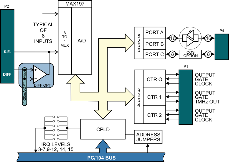
ANALOG INPUTS
The Analog Inputs feature software programmable gain with ranges of 0-5V, 0-10V, ±5V, and ±10V. The configuration employs an instrumentation pre-amplifier per channel which allows for differential inputs, 200V Common Mode Rejection, high input impedance, and optional factory channel by channel pre-settable gain (1-200) to accommodate low-level inputs from sensors. Inputs 4-20mA are available as a factory-installable option.
COUNTER TIMERS
The circuit uses an 82C54 (3 sixteen bit counter/timers). The user has access to each counter/timer’s gate, clock, and output signals. The output of counter two can be used to generate an interrupt. The software package supports counting events, frequency output, pulse and frequency measurement.
DIGITAL I/O
The circuit uses an 82C55A PPI with mode 0 supported. Ports A and B (16 lines) are buffered and pulled up to 5V. Port C features Change of State detection.
SOFTWARE
The package includes a setup program detailing all jumper settings. Also included are IRQ drivers, samples for DOS, and utilities for Windows operating systems (Windows 98, NT/2000, and NT/XP). Full register-level support for use in custom real-time or embedded operating systems.
Specifications
Analog Inputs
- No. of Channels: Eight true differential.
- Programmable Ranges: 0-5V, 0-10V, ±5V, ±10V, (4-20mA as a factory option)
- Conversion Frequency: 100K Samples per Second
- Resolution: 12-Bit
- Differential Input Impedance: 2Meg Ohms w/pre-amp
- Preamplifier gain: 1 standard, up to 200 upon request
- Reference Output Voltage: 4.096V ±0.02V
- Common Mode Voltage: ±200V
- Common Mode Rejection Ratio: 86dB typical
- Integral Nonlinearity: ±1 LSB maximum
- Full Power-Down Mode: 1µA maximum
- Standby Power-Down Mode: 400µA maximum
- Accuracy: 0.2% of full scale
- Gain Temperature Coefficient: 6 ppm / °C typical, bipolar; 8ppm/ °C typical, unipolar
- Noise levels: ±1 LSB typical
- A/D triggering methods Ctr/Tmr or Software
Digital Inputs/Outputs
- Programmable Peripheral Int.: 82C55A
- Channels: 24, pulled up to 5V via 10K (or pulled down to ground)
- Buffered Channels: 16 (ports A & B)
- Sink & Source Current: 64mA & 32mA respectively
- Modes supported: Mode 0 (1 and 2 are factory options)
- Change of State Detection 8 inputs (port C)
Counter/Timer
- Peripheral Interface Timer: Type 82C54
- Counters 3 x 16-Bit down counters
- Clock Frequency Output: 1Mhz
- Inputs/Outputs Fully Buffered
- Native Modes: Pulse on terminal count, retriggerable one-shot, rate generator, square wave, software triggered strobe, hardware triggered strobe.
- Software Support: Event Counter, Frequency Output, Frequency and Pulse Measurement
General
- Power Required: 5V @ 40mA, ±12 @ 30mA; with optional ±12V DC/DC conv. 5V @ 240mA
- Environmental: 0°C to 70°C standard, optional without DC/DC converter -40°C to 85°C
- Interrupt Requests: Eleven channels, IRQ 3-7, 9-12, 14, 15
- Interrupt Status Register: Indicates source(s) of interrupt
- Interrupt Enable/Disable: Software Controlled

CE testing & approval must be done at the system level, in the designed enclosure, and is not done on individual boards.